 |
Deutsch
T R 1
Software for Girder Calculation
(C) Copyright by HEXAGON 1997-2025
Girder Calculation with TR1
For any cross-section, TR1 calculates bending and tension stress,
deflection, bending angle and natural frequency of fixed clamped or girders
mounted in two to five places.
Quick Input
At Quick Input, you can enter girder dimensions, bedding, material properties, forces, path load and bending moment altogether in one dialogue window. "Calc" button calculates the girder and shows results as selected at "Display" options.

Cross-section
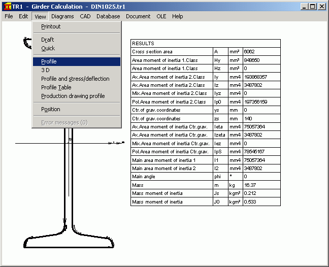
The girder cross-section can be taken from the data base, loaded from a
DXF file, or defined by entering coordinates. TR1 calculates surface
moment of inertia, axis of gravity and main axis of the profile cross-section.
Profile data base
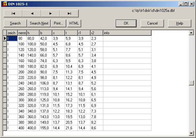 Data base files are included for girders in accordance with DIN 1024,
double-T in accordance with DIN 1025, L-girders in accordance with DIN
1029, double-L girders in accordance with DIN 1027, L-irons in accordance
with DIN 1028, U-irons in accordance with DIN 1026 and flat steel in
accordance with DIN 1017. Click on the required profile and TR1 generates
the geometry and calculates the surface moment of inertia, center of
gravity, position of the zero axis and weight of the girder.
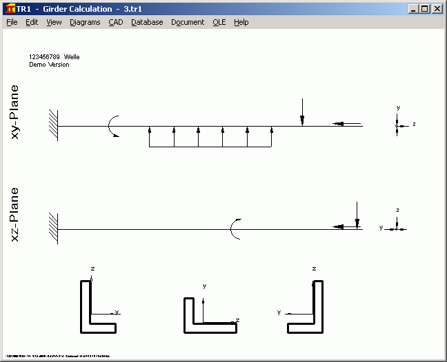
Load
Up to 50 individual forces, path loads, bending moments and axial forces
can be defined as load along the x axis, for any angle in the yz
coordinate system.
Bearing area
TR1 calculates girders with statically determined bearing area with fixed/loose
bearings or fixed clamping. In addition, statically undetermined bearing
area girders with three, four or five bearing area positions can also be calculated.
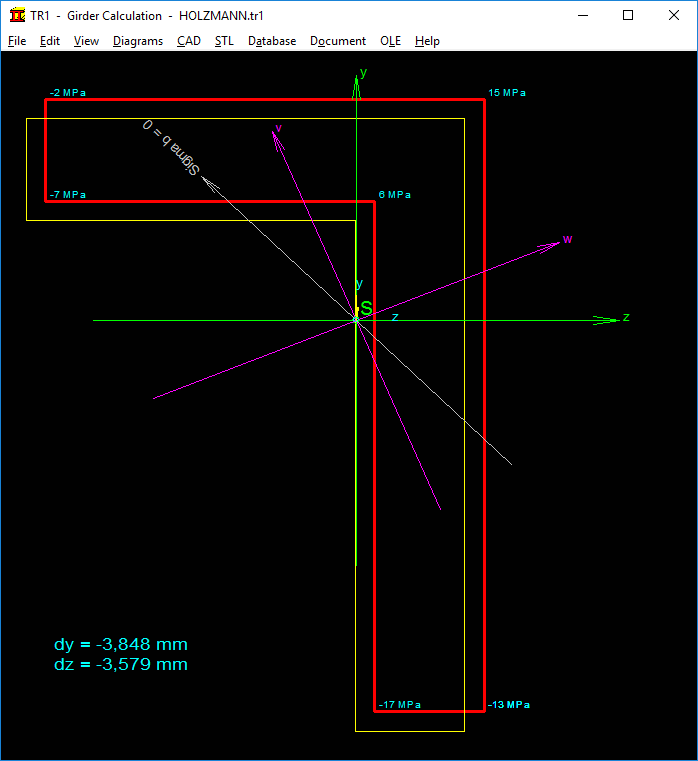
Oblique Bending
The deflection with oblique bending occurs perpendicular to the zero line,
not on the load plane. TR1 calculates deflection and the stress curve
from two overlapping straight deflections for both main axes of the
girder cross-section.
Stress distribution in the cross-section
TR1 draws the girder profile with the occuring stress for every point.
The contour displacement caused by bending is also sketched.
Material data base
The most important steels are included in the data base delivered with the
program. You can access other steels and non-iron metals by accessing the WST1
material data base.
Diagrams
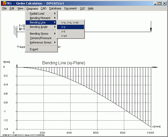
You can obtain important information by veiwing the curves for shearing
force, bending moment, bending angle, bending line, bending stress and
reference stress. You can print the diagrams out, transfer them to your
documentation via DXF files or the Windows clipboard.
Printout
The printout contains all the input data, the extreme values for bending
moment, bending line, bending stress, shearing stress and reference
stress, weight, surface moment of inertia, mass moment of inertia, center
of gravity, inherent forces, bending angle of the bearing area positions and
material values.
CAD Interface
After you have calculated a girder with TR1, you can export a true-scale
drawing of the profile cross-section or a 3D drawing of the girder to your CAD system via DXF or IGES
files.
HEXAGON Help System
As required, you can display an explanation and auxiliary picture for each
of the input entries. For input errors and when limiting values are
exceeded TR1 will automatically display an error message. For each error
message you can obtain a more detailed description of the error and a
remedy suggestion.
Hard and software requirements
TR1 is available as 32-bit and 64-bit application for Windows 11, Windows 10, Windows 7.
Scope of Delivery
TR1 program with sample data, auxiliary pictures and help text, a detailed user manual (pdf), input forms, license for unlimited time use and update service.
Information and update service
HEXAGON software is continually updated and improved. Customers are
regularly informed about updates and new releases.
Price list |
Order |
E-Mail |
Return

 |
Deutsch


