Spring Material to ASTM
American spring materials according to ASTM specifications were added to the spring material databases of all spring programs. Material data to DIN and ASTM are not comparable directly.
DIN defines permissible shear stress as 0.56*Rm for compression springs and 0.45*Rm for extension springs. According to ASTM, the permissible shear stress depends on material type (0.35*Rm to 0.45*Rm). However, from the Goodman Diagrams, one can gets this values:
|
ASTM Music Wire |
ASTM 18-8 (302) |
DIN |
|
|
Compression spring |
Tau perm = 0.5 Rm |
Tau zul = 0.45 Rm |
Tau zul = 0.56 Rm |
|
Extension spring |
Tau perm = 0.35 Rm |
Tau zul = 0.36 Rm |
Tau zul = 0.45 Rm |
|
Torsion spring, spiral spring |
Sigma perm = 0.66 Rm |
Sigma perm = 0.63 Rm |
Sigma perm = 0.7 Rm |
New Materials in FEDWST.DBF:
Music Wire, Hard Drawn, Oil Tempered, Chrome Vanadium, Chrome Silicon, AISI 302/304(18-8), 17-7 PH. Goodman-Diagrams are available for Music Wire and 18-8. Relaxation data are not available until now.
Spring Material Database
Material composition was modified according to EN 10270:
1.4310: X 12 CrNi 17 7 to X10CrNi18-8
1.4401: X 5 CrNiMo 18 10 to X5CrNiMo17-12-2
All material data stay the same.
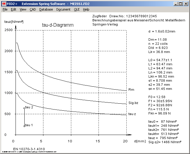
FED1,2: tau-d-Diagram

Curve of tensile strength has been added to the tau-d(perm. Shear stress - wire diameter) diagram. A third curve in FED2+ shows the permissible bending stress (in the loop).
Spring Software - self-defined material
If you select self-defined material and enter the material data, the program cannot calculate life expectation and Goodman diagram nor relaxation. Better choose material from database.
Spring Software - Relaxation Diagrams
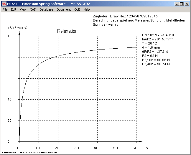
Labeling of 2 relaxation diagrams had to be corrected (dF/F -> F2 for relaxation of spring load F2 as function of time, and dF/F -> dF/dFmax for relative relaxation as function of time.
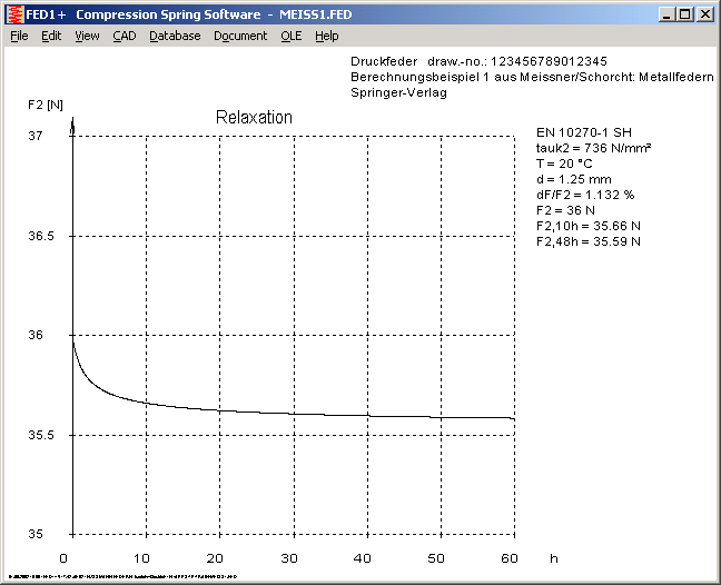
To change diagram limits (here 0..40 -> 35..37), go to "File-Settings-CAD" mark checkbox and select diagram at "CAD->Diagrams".
WN4 - Fillet Radius
WN4 calculates with minimum fillet radius of 0.05/P for strength calculation.
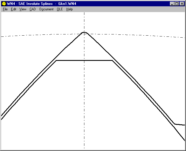
WN4 - Tooth Drawing
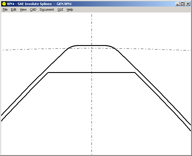
Major diameter Dri was used for tooth drawing of internal splines, and minor diameter Dre for external splines. Tooth root diameters may be between this values and form diameters Dfi and Dfe, large tolerances are possible here. New version of WN4 now uses average values (Dri+Dfi)/2 and (Dre+Dfe)/2 for tooth drawings.
SR1 - Pressure Load
For pressure load (Fau<0), the critical point is not the residual clamping force FKR between the clamping plates, but the "residual bearing force FSR below the bearing face of the bolt.
FSR = FV + FSA with FSA<0 for FA<0
In older versions, for FAu<0 SR1 calculated FKR = FV + FPA with FPA<0 for FA<0.
The new Version also calculates a load-extension diagram for Fau<0.
If FAo>0 and Fau<0, SR1 draws the lines for min and max condition.
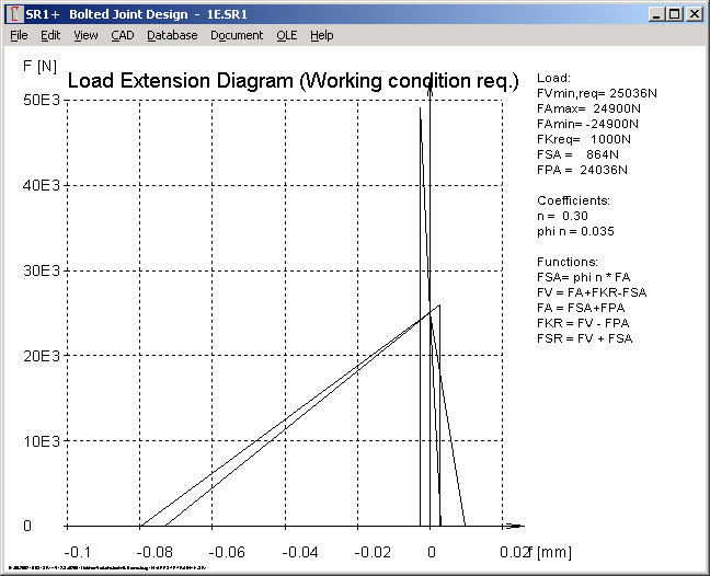
Application example with axial load FA=+/- 24900 (example 1 with Fau = - FAo).
Production drawing - Additional column added
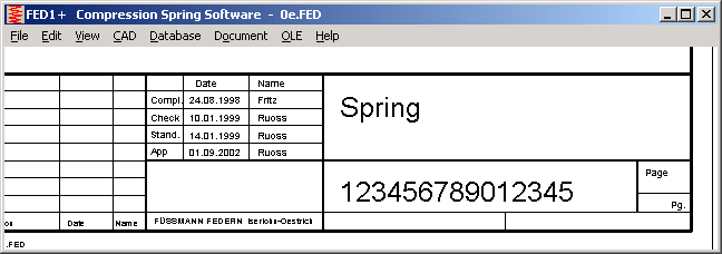
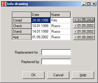
Besides Compl., Check and Stand., a new free-definable column was added.
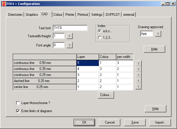
At "File->Settings->CAD", you can enter the label of the column. Default value is "App".
At "Document->Drawing Info" you can enter date and name.
Pricelist | Order | Update Order | E-Mail | Homepage