
 | English
| Deutsch
FED2+: Reduce stresse by means of reduced loop diameter and coil diameter

If a tension spring breaks, it usually breaks in the transition from the spring body into the loop, where the torsional stress changes into a bending stress.
Torsional stress in the spring body: tau = Mt / Wt = F * Dm / 2 / (pi / 16 * d³)
Bending stress at the loop transition: Sigmab = Mb / Wb = F * Dm / 2 / (pi / 32 * d³)
Tensile stress in loop: Sigma = F / A = F / (pi / 4 * d²)
The tensile stress is negligibly small, its share is only relevant if the coil ratio Dm / d is small. The notch effect due to the bending radius and coil ratio is more important.
The bending stress is twice as high as the torsional stress, but the permissible bending stress in general mechanical engineering is also about twice as large as the permissible torsional stress. But the spring calculation according to EN 13906 is a little different: tau perm = 56% Rm for compression springs and 45% Rm for tension springs, Sigmabzul = 70% Rm for ltorsion springs. The stress on tension springs in the transition from the spring body to the loop is comparable to torsion springs in the transition from spring body to leg and is also calculated in this way in FED2+.
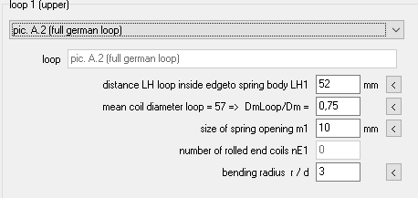
In order to reduce bending stress and torsional stress in the body-loop transition, the loop diameter and the coil diameter at the loop transition can be reduced, which reduces the lever arm DmLoop / 2. In FED2+ you can now enter a smaller coil diameter and loop diameter by entering a factor DmLoop / Dm. The loop diameter is then taken into account when calculating the bending stress in the loop.
FED2+: Reference Stress at Loop Transistion

As another new option (not yet verified), you can calculate a reference stress at spring force F2 if you tick the appropriate box under "Edit \ Calculation method". The reference stress Sigmav2loop in the loop transition must be less than the tensile strength Rm.
FED2+: Quick3 Table with empty Sigma column for tension springs without loops

In the table in the Quick3 view, the bending stress Sigma now is only displayed if a loop has been selected. No bending stress occurs if hooks, threaded bolts, threaded plugs or screw tabs are rolled in, which is why the Sigma column remains empty.
Spring Materials – Comparison of standards EN10270-1, ISO 4858-2, GB/T 4357
Patented drawn spring steel wire is standardized in EN 10270-1, wire types SL, SM, SH, DM, DH. "S" stands for static, "D" for dynamic. Tensile strength class "L" for low, "M" for middle, "H" for high.
The mechanical properties in ISO 4858-2 are the same as EN 10270-1. The only difference is that wire type DM according to ISO 4858-2: 2002 is available from 0.08 mm wire diameter, and according to EN 10270-1 only from 0.3 mm. And the Chinese GB / T 4357 is again exactly the same as ISO 4858-2.
ISO 4858 is from 2002, there is no newer edition.
GB / T 4357 is from 2009 and identical to ISO 4858-2: 2002
The current EN 10270-1 is from 2017. In the mechanical properties, a typo in the tensile strength of SM and DM at d = 15mm has been corrected compared to EN 10270-2: 2012 and EN 10270-2: 2008. In EN 10270-2: 2001 and thus also in ISO 4858-2 and GB / T 4357, this value is still correct.
Only the tables with the mechanical properties and tolerances are relevant for the spring programs, other contents such as delivery forms and delivery conditions were not compared.
The only difference when comparing the table with mechanical properties of the standard from 2017 with that from 2001 is that the diameter ranges are delimited mathematically correctly in the newer standard ("14 <d <= 15", "15 <d <= 16" instead of "d to 15", "d to 16"). The strength values in the standards from 2001 and 2017 are exactly the same.
FED1+: Error message "F2,48h < F2min" not for zero tolerances

The error message means that the relaxation of the spring at F2 is greater than the tolerance of the spring force F2. However, this error message does not apply in one case: If you want to set a tolerance for spring force F1, but not for spring force F2, there is a trick to set upper and lower tolerance 0. The tolerance is then not 0, but free, the spring force F2 is then output without tolerance. The error messages "F2,48h <F2min" now only appear if a "correct" tolerance has been entered for the spring force F2.
FED6: Buckling travel sk added in Quick3,4 View

In FED6 Quick3 View, buckling travel and buckling spring length has been added.
FED8, 11,15, 16: Italian Release
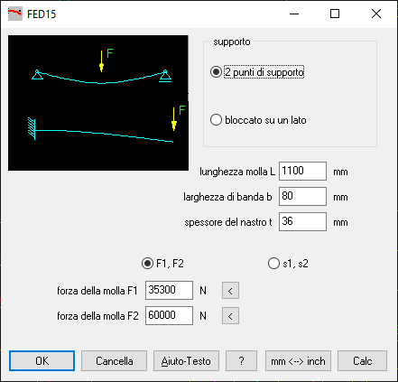
There is now an Italian version of FED8, FED11, FED15, FED16. The program is in Italian, only manual, help texts and help pictures are in English. Apart from FED10 and FED12, all spring programs are now also available in Italian
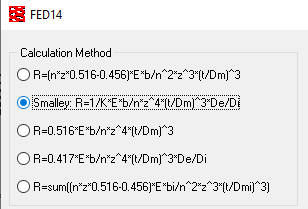
FED14: Factor K according to Smalley
For the number of waves 7.0 - 9.5, a factor K = 2.9 instead of 2.3 was used in the Smalley spring rate calculation. Fixed in version 2.5
FED14 – Torsional Spring Rate

With helical wave springs it is important that the wave crests lie exactly on top of each other, otherwise in extreme cases the wave crests can be pressed into the wave troughs by twisting. Then the measured spring forces are smaller than the calculated values. The forces at block length then match again, because then there are no more wave crests and wave troughs.
The torsion spring rate is now also calculated and printed out in FED14. As "Rtorsion" in Nmm / ° and as "Rto / r" in N / ° and as "Rto / r²" in N / mm (in the mean coil diameter). If the torsion spring rate is small compared to the axial spring rate, then there is a great risk that the helical wave spring will twist under load and the wave crests will be pressed into the wave troughs. In the Quick3 view, "R torsion" is only output if it is at least 5 times smaller than the spring rate R. Also important in this context is the spring rate "R torsion * n", that is the torsion spring rate between two windings lying on top of each other, while "R torsion "Or" Rto / r² "is the torsion spring rate of the entire spring in relation to the mean winding diameter.
WN2,3,6,7,8,9,10,11,12: Re=Rm for brittle Material
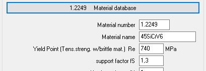
For brittle materials, one can use the tensile strength Rm instead of the yield strength Re to determine the permissible surface pressure plim. When selecting from the material database, Rm is now used instead of Re, if Re = 0.
WN4, WN5: Safety factors for compressive load and equivalent stress
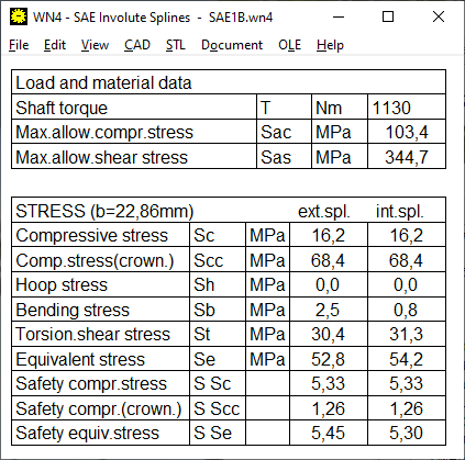
The strength of SAE splined shaft connections is calculated according to the SAE Design Guide for Involute Splines. If permissible stress is exceeded, errors are reported. WN4 and WN5 now also calculate safety factors:
Equivalent stress safety S Se = Sas / Se * 2 * Lf / (Ko * Km)
Compressive stress safety S Sc = Sac / Sc * Lw / (Ko * Km)
Compressive stress (crown.) Safety S Scc = Sac / Scc * Lw / (Ko * Km)
WN4, WN5: Export WNXE, WN2+, ZAR1+
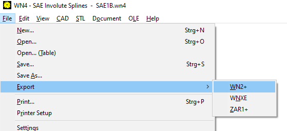
You can now export spline gears to SAE and ISO 4156 to file format WNX for WNXE, WN2 for WN2 + and ZAR for ZAR1 +. Exporting to WNXE makes sense if you e.g. want to design a splined shaft with a larger or smaller backlash for a standard splined hub. An application for export to WN2+ (only possible with the Plus version) would be a strength calculation according to DIN 5480 for a spline according to ANSI B92.1 or ISO 4156. And in ZAR1+ you can export the dimensions to see how a splined shaft is designed as spur gear.
ZAR5, ZAR7: Ring Gear for square housing
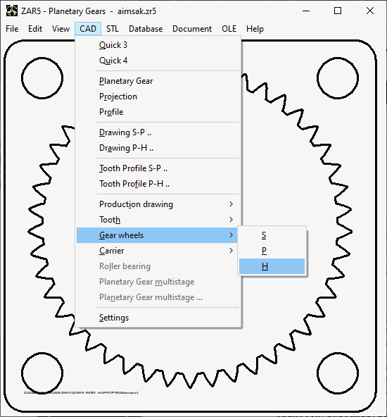
The ring gear of planetary gears can now also be printed with a square outer contour. The rim diameter dB is then the edge length a. As with a round outer diameter, fastening holes can be defined on a bolt circle. The number of holes is always 4 in this case, the hole circle diameter can be larger and dB smaller than with a cylindrical ring gear.
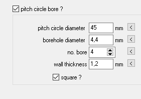
ZAR5, ZAR7, ZAR8: Housing cover for planetary gear (carrier side and sun wheel side)
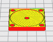
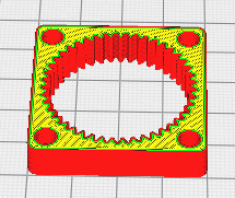
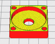
Under "STL" in the menu you can now also print housings for planetary gears with the 3D printer. The outer contour can be round or square.
Scale for DXF drawings

In the CAD settings, there is a new option to enlarge or reduce drawings as a DXF or TXT file. If you e.g. you want to output the DXF file in inches, you can configure a scale 1 / 25.4 = 0.03937.
Windows 10 Updates manipulate Hard Drive
Unfortunately, Windows 7 is no longer supported by Microsoft, so most users will be forced to switch to Windows 10. Because Windws 10 updates sometimes change partitions on the hard disk (usually the hard disk has "shrunk" by 0.5 MB afterwards), you should not install HEXAGON software on the Windows partition C:, but on a different partition or drive, if available. Else key code becomes invalid and you have to request a new key code. You can even install HEXAGON software on an external hard drive, then you can simply take the software with you when you move to another PC later. If you change the serial number or hard disk parameters through Win10 updates, you will need new key codes every time.
Cycling in the City
20 years ago, Berlin was a paradise for bike tourists. A red wheel lane was set up on the sidewalks for cycling, and you could safely explore the city on a bicycle. Presumably to protect pedestrians, the wheel tracks were moved to the street, with obvious consequences in the accident statistics of the cyclists killed. It is even more dangerous if the wheel track runs alongside parked cars. If the car doors are opened carelessly, the cyclist has no chance, because from behind it is not possible to tell whether someone is sitting in a parked vehicle or not. Perhaps a sensor in the exterior mirror would be a solution, which switches on a child lock on the driver's door in the event of danger and prevents the careless opening of the door.
Intelligent traffic light: "red arrow" instead of "right turn assistant"
Because trucks, minibuses and SUVs overlook straight-ahead cyclists when turning right, complicated right-turn assistants with cameras and monitors are recommended for trucks. This would be much easier with an intelligent traffic light for right-turners, which only turns green when cyclists driving straight ahead have left the collision area. Compared to the sensors for a self-driving car, the effort for a traffic light with an intelligent red arrow would be a no brainer. In this context, sensors for intelligent traffic light and traffic flow controls could also be installed. It is not easy to program traffic lights optimally. Nevertheless, it is annoying when everyone is waiting at a traffic light and nobody is driving. Poorly programmed traffic lights cost transporters a lot of time and money, 24 hours a day, for years.