 | English
| Deutsch
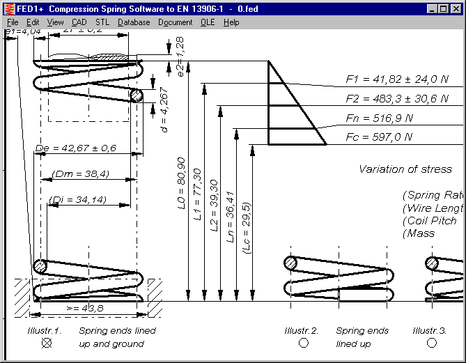
FED1+: (Lc = x.x) in Production Drawing

If production compensation is defined by number of coils (n), block length cannot be a control dimension. Block length Lc is printed without tolerance in this case. Additionally, it is drawn in brackets in the latest version of FED1+.

FED15, FED16: Input Material Data
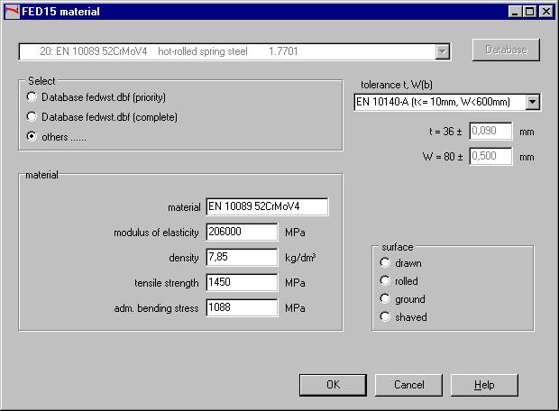
As alternative to pick from database, you can input base properties of material (E module, tensile strength, yield strength, permissible bending stress) directly now.
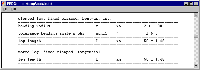
FED3+: Tolerance of bending angle corrected
Tolerance of bending angle according to quality 1,2,3 of DIN 2194 of torsion springs with bent legs was not calculated correctly. Tolerance Aphi is listed in the standard printout only, not in production drawing nor Quick view. Thanks to Mr. Demmelbauer of Hutter & Schrantz steel springs for hint and documents.
ZAR1+ .. ZAR8: Modifications in Material database
Properties were slightly modified for nodular cast iron:
EN-GJS-400: HB from 180 into 170
EN-GJS-600: E-Module from 180 GPa into 174 Gpa
EN-GJS-1000: E-Module from 190 GPa into 168 GPa, µ from 0.29 into 0.27, density from 7.2 into 7.1.
Thanks to Mr. Schulze of BS Technik for hints and documents.
ZAR1+,ZAR2,ZAR5,ZAR6,ZAR7,ZAR8: Load spectrum according to ISO 6336-6
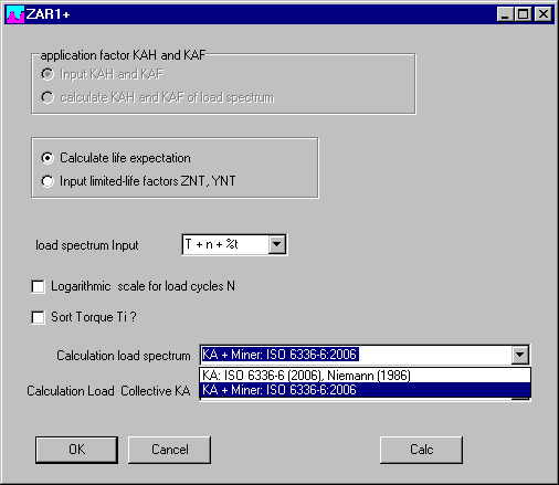
Until now, our ZAR-Software used calculation method according to Niemann to calculate application factors KA from load spectrum. This method is described in ISO 6336-6 annex A with purpose of a first estimation only. So we have added the preferred method to Palmgren-Miner as described in ISO 6336-6. Select both methods at Edit\Load spectrum\Config.
Calculation must be separate for gear 1 and gear 2 to this method. Gear 2 differs in speed and number of cycles by transmission ratio and number of tooth contacts per rotation:
N2 = N1 * z1/z2 * e2/e1
with 1 = pinion, 2 = wheel, N = number of cycles, z = number of teeth, e = tooth contacts per rotation
ZAR1+,ZAR2,ZAR5,ZAR6,ZAR7,ZAR8: Input Period

New input is period time for the load spectrum (including idle time). Idle time is calculated as difference of period and sum of load spectrum. If input is 0 or less than sum of load spectrum, idle time is 0 and period is set to sum of load spectrum. Normally, required lifetime of the gear is set as period time. But you can also describe the load spectrum for a period of days or hours. Period time unit can be set to seconds, minutes, hours, days or years.
ZAR1+,ZAR2,ZAR5,ZAR6,ZAR7,ZAR8: Load spectrum: lifetime to ISO 6336-6
Both calculation methods (KA and Miner) can be compared by comparing the calculated lifetime. Because idle time can be considered now in Miner calculation, but not in KA calculation, one must compare lifetime at 100% duty cycle.
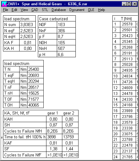
Calculation of lifetime by Miner sum considers all load bins, KA calculation considers only bins with torque higher than 50% of nominal torque or until the sum of cycles is higher than fatigue safe limit of the S/N curve.
Application example table 2 of ISO 6336-6 calculates 3900 hours until pitting for the pinion to KA method, and 6000 hours according to Miner method. If idle time of 6E6 s in 70 days is considered, time until pitting (gear1) is 5455621 hours = 630 years. ISO 6336 annex C calculates 30 years with a safety factor of 1.428. Idle time of 99,9% is extremely high in this example, in 30 years the gear is on duty for 10 days only.
ZAR1+,ZAR2,ZAR5,ZAR6,ZAR7,ZAR8: Load spectrum diagrams
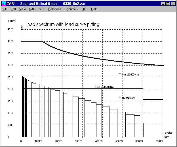
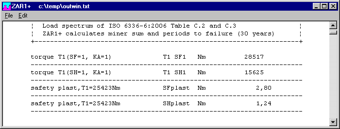
Limits of the y axis (torque) has been changed, so that S/N curve can be drawn in any case. Equivalent S/N curve of the load spectrum is no longer drawn nor the corresponding parameters TnFeq, TnHeq, T0Feq and T0Heq, as not mentioned in ISO 6336-6. Scale of the x axis (cycles) can be drawn linear or logarithmic. Program calculates torque for safety factors SH=1 and SF=1 in an iteration, as well as static safety SHplast and SFplast for the highest (1st) torque of the load spectrum.
ZAR1+,ZAR2,ZAR5,ZAR6,ZAR7,ZAR8: Input load bins with different speed
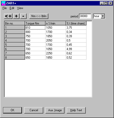
In standard input of load spectrum, you can input torque or power and speed, program calculates and shows relation to nominal values in %.
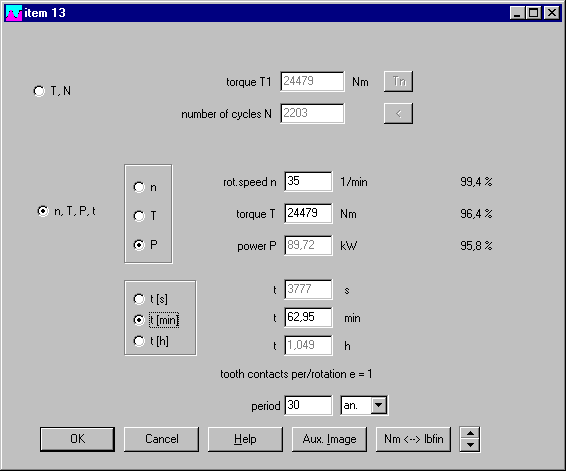
At input "n,T,P,t" you enter speed, torque or power and time for each bin and program calculates cycles. These data have not been saved until now (T and N only), values of n,P,t cannot be recalculated if speed varies. Now, speed of each bin will be saved. If not saved, nominal speed is used for all bins.
Also at "Edit\Load Spectrum\Table" you can input speed for each bin.
ZAR1+,ZAR2,ZAR5,ZAR6,ZAR7,ZAR8: Load spectrum Export/Import

For exchange with MS-Excel a new Export/Import Excel has been added in the menu. Or you can use Copy and Paste for import/export of load spectrum tables with any Windows spreadsheet. Furthermore, you can import or export load bins by means of KOL file. The proprietary KOL format was extended by speed for each bin.
ZAR1+,ZAR2,ZAR5,ZAR6,ZAR7,ZAR8: Sort Load Spectrum

Until now, you had to input bins of load cycles in correct order, beginning with the highest torque. Now you can enter bins unsorted, and let sort by ZAR software.
ZAR1+,ZAR2,ZAR5,ZAR6,ZAR7,ZAR8: Load spectrum tables
Tables with intermediate results of load spectrum calculation to Palmgren-Miner can be listed in tables. Share of cycles (N %) and share of damage (tF %) is listed for each bin (similar as in FED1+ load spectrum). Share of damage for each bin is calculated as fi = Ui / Miner sum.

Cause 4 Miner sums have to be calculated (pitting, tooth root stress gear 1 and gear 2), you get a huge number of data that can be listed in 3 tables.

SR1+: Self-defined elasticity for calculation of deltaP
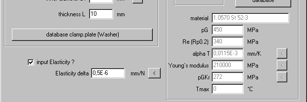
At input of clamping plates, you can input elasticity as alternative to calculation by SR1+. Now it was found that self-defined elasticity was considered only if "deformation sleeve" was configured. New version now considers self-defined elasticity for both, calculation by deformation sleeves and by deformation cone. Thanks to Mr. Huegl of Leadec Engineering for hint and documents.
WST1: Calculate size factor from size exponent and material thickness
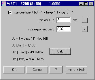
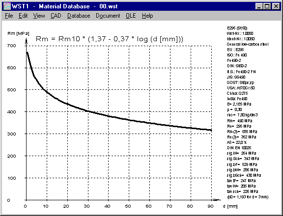
Until now, WST1 calculated size factor for material groups 1 to 27 (steel) to the formula b0=1+0.2*[1-log(d)]. Material properties of the database are based on material thickness (material diameter) of 10 mm. Cause size factor for different materials and different heat treatment differs, now you can input material exponent for calculation of the size factor. First you have to hook on that size factor must be considered. Material exponent for steel lies between 0.1 and 0.4.
Sigma(d) = Sigma(d10) * b0(d)
b0(d) = 1 + bexp [1 – log (d)]
WST1: Fatigue strength 1.4310 and 1.4568
Fatigue strength stress limits for 1.4310 and 1.4568 have been added, so that Smith-Diagram, Haigh-Diagram, Goodman-Diagram and S/N curve can be drawn for these materials.
WST1: Nodular cast iron: new materials and modifications
Modifications of E module and stress limits for this materials:
EN-GJS-400, EN-GJS-500, EN-GJS-700, EN-GJS-800
New materials in WST1: EN-GJS-1000-5, EN-GJS-1050-6, EN-GJS-1200-2, EN-GJS-1400-1, EN-GJV-400
LG1, ZAR5, ZAR7, ZAR8, WL1+: Full cplm. needle bearing and roller bearing
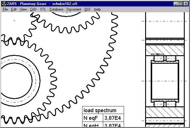
If not enough space for roller bearings with inner and outer ring, bearing of planet wheels can be a cylindrical roller bearing without outer ring, or needles only between planet bolt and planet wheel bore without cage.
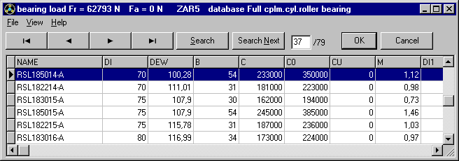
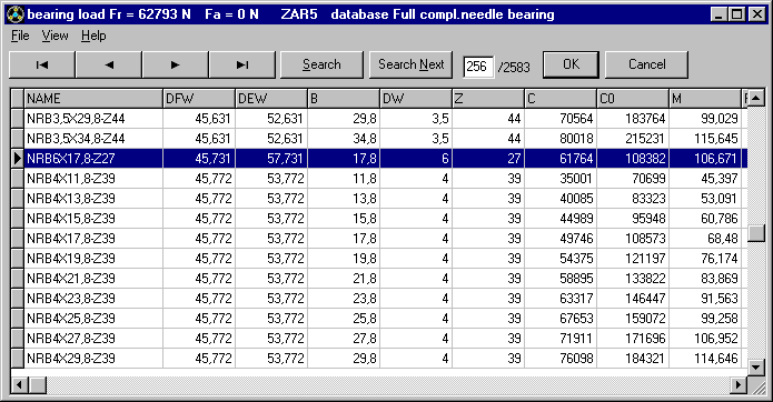
For full compl. needle bearings, clearance between rollers is calculated by the program (pitch diameter clearance TES = 5E-3 Z according to Schaeffler). Then roller race diameter of shaft and bore can be calculated. To select full compl.needle bearings as known from other roller bearing databases, a new database file was created for pin diameters of 1mm until 6mm and pin length of 5.8mm until 39.8mm and 10 until 50 pins, with calculated race diameters, rated load C and C0 and mass. This results in a new database file with 2500 records.
Windows 10 – Automatic Updates
Some customers got a key code error after Windows 10 automatic update. The reason is, that sometimes Windows 10 update modifies partitions of the hard disk, so that after update the size of the hard disk shrinks by 0.5 GB. I do not know what Microsoft makes with the hidden partition. Anyway, you have to delete *.cod files in the HEXAGON program folders, then run programs and send key code requests to get new key codes.
Tip: Where to install HEXAGON-Software
If your computer has more than one hard disks or logical drives, better install HEXAGON software on another drive besides Windows system drive, if your operating system is Windows 10.
If your PC has a small and fast SSD and a large, slower hard disk, install HEXAGON software on the (slow) hard disk, if Windows 10 runs on the SSD. If you want to accelerate HEXAGON software by means of your SSD, then configure a folder on the SSD as temporary drive (at "File\Settings\Directories").

Tip: Network version: Set "copy DBF -> TEMP"

This new option copies all dbf files at program start into the temp folder. This accelerates program speed enormously and reduces network traffic, if temp directory is a local drive.
Temporary drive must be as fast as possible (RAM-Disk, SSD or hard disk, but no network drive!)
Tip: Program start by double click into calculation file reports error after update?
HEXAGON software reports a database error since update or change of program path? Probably cfg file with configured directories could not be found. Copy cfg file into "c:\hexagon\", then it should start without error.