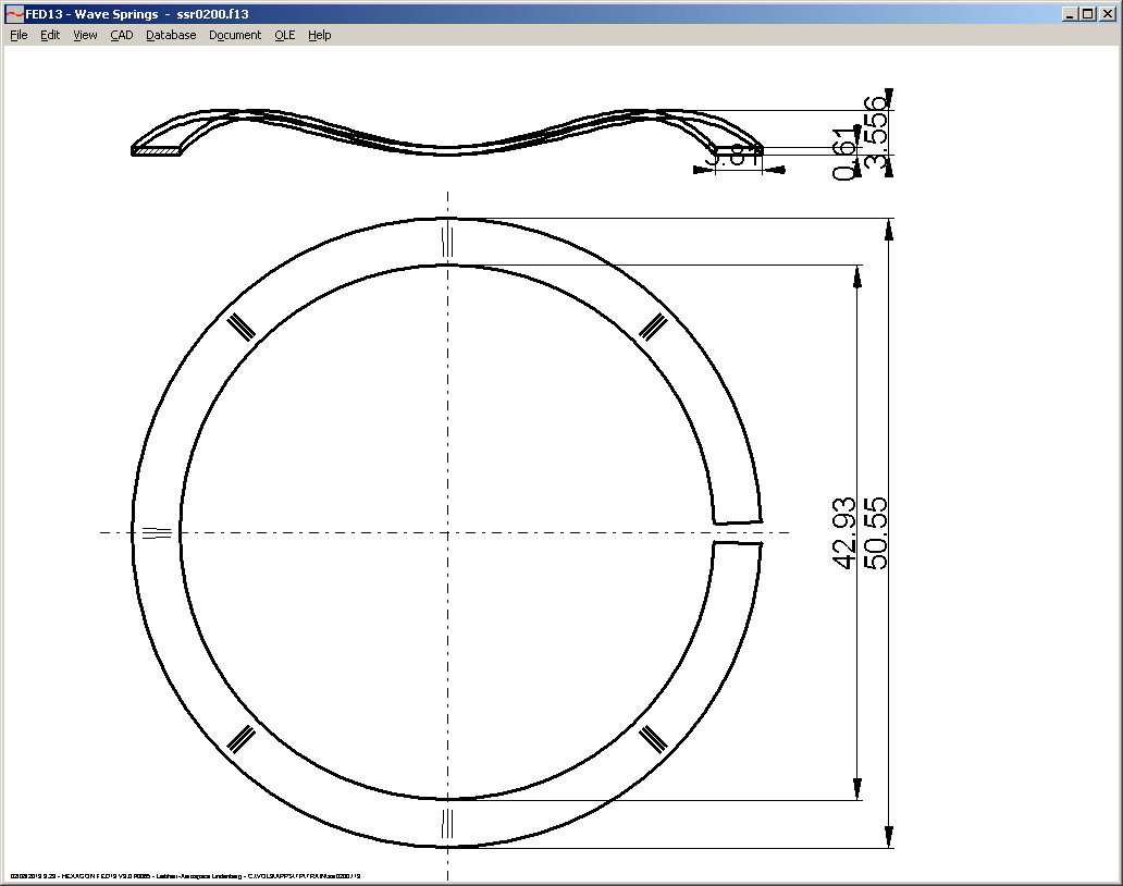
FED13 - Wave Springs: Closed or Open

Until now, FED13 calculated wave springs made from a disc (closed type). Nowadays, also open wave springs are in use, made from strip steel like a helical spring with one or even more coils. In FED13, you can now select open or closed wave springs and calculate this spring type as well.
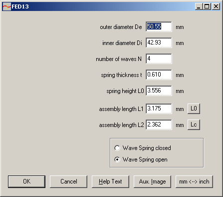
Spring loads and spring rate of open wave springs is much lower than for closed wave springs, at least for low coil ratio D/b.
FED13 - Quick3 View
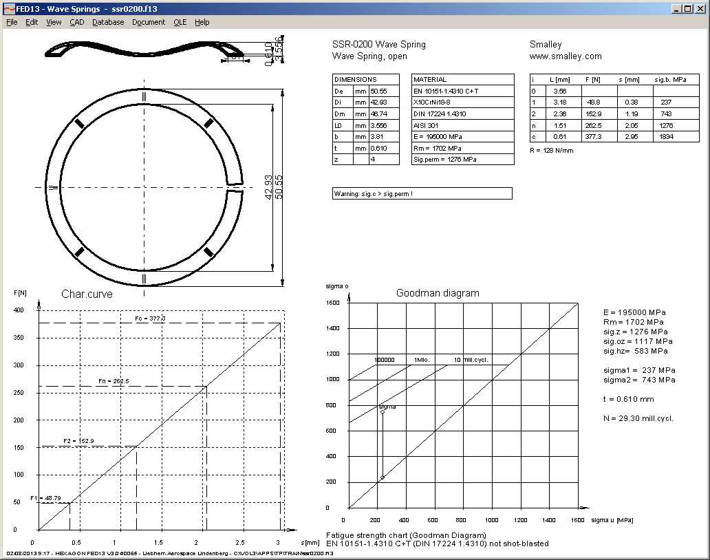
Table with material data and spring rate has been added to Quick3 view in FED13.
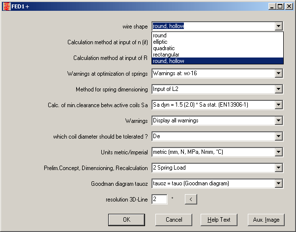
FED1+ Helical Compression Springs made from hollow wire
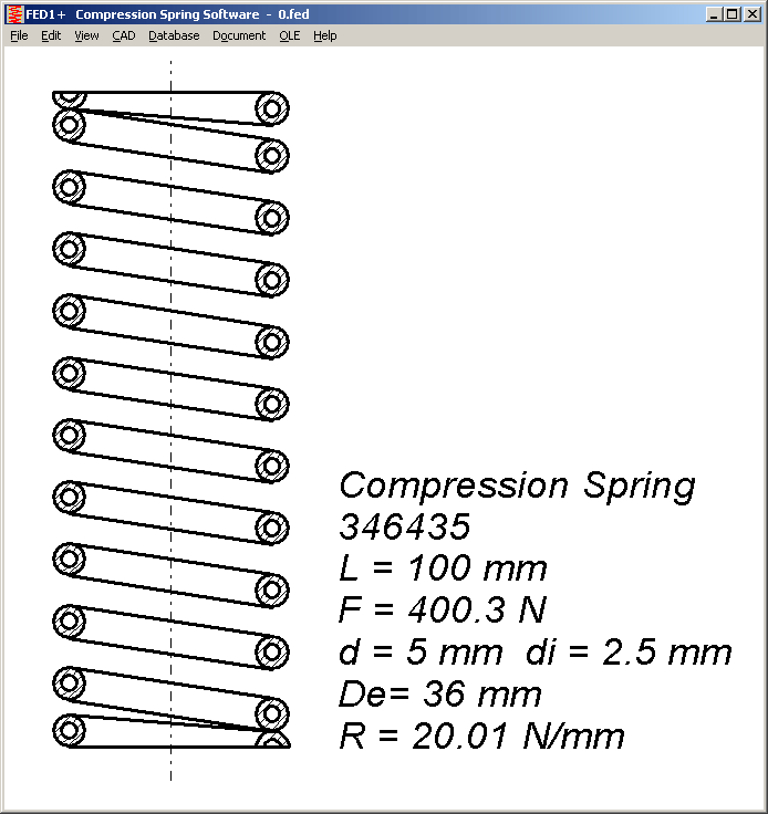
Springs from hollow wire can be preferred, if moving mass should be reduced. To reduce spring mass by 50%, inner wire diameter must be 0.707 d. In this case, spring load and spring rate will be reduced by 25% only, and maximum shear stress remains the same.
FED1+ Natural Frequency
Natural frequency is now calculated for springs of square, rectangular, elliptic and circular tube wire as well. Until now, only springs from round wire had been calculated according to EN 13906:
fe = 3560 d / (n * Dmē) * sqrt(G / density)
This formula can be converted into a form more simple and valid for other wire sections as well:
fe = 500 sqrt(R / m0) with R in N/mm and m in g
whereas m0 means the mass of the active coils only (end coils =0).
fe is the natural frequency of the spring for the case that both ends are fixed. Amplitude is 0 at the ends, and maximum in the middle of the spring length.
For a spring-mass-system, this formula is used:
f0 = sqrt(R / (m+mspring/3)) / (2 * pi)
In this case, spring is fixed on one end, and the other end oscillates with external mass m. Amplitude is 0 at fixed end, and maximum at the other spring end. Mass of the spring is considered only 1/3 compared with external mass, because oscillating spring travel decreases against fixed spring end.
FED3+ Natural Frequency
In FED3+, "fe" is the natural torsion frequency of a helical coiled torsion spring with a clamped leg and a moved leg. Moment of inertia of the moved leg is considered in "fe". In FED1+ and FED2+, "fe" means natural frequency of the spring body for fixed spring ends. In FED3+, an equivalent torsional natural frequency "fd" of the spring body has been added in the printout. Natural frequencies "fe" and "fd" are also calculated for square, rectangular, elliptic and oval wire section now.
FED1+ Lateral Deflection and Buckling
If you input radial load FQ at "Edit->Application", FED1+ calculates transverse deflection sQ, transverse spring rate RQ, and radial natural frequency fq. Radial spring travel sQ and radial spring rate RQ depend on axial spring travel s. Three new diagrams have been added therefore into FED1+: RQ-s with radial spring rate, sQ-s with radial spring travel, and fq-s with radial natural frequency as function of axial spring travel s.
Here example diagrams for a compression spring that buckles between spring travel s2 and sn:
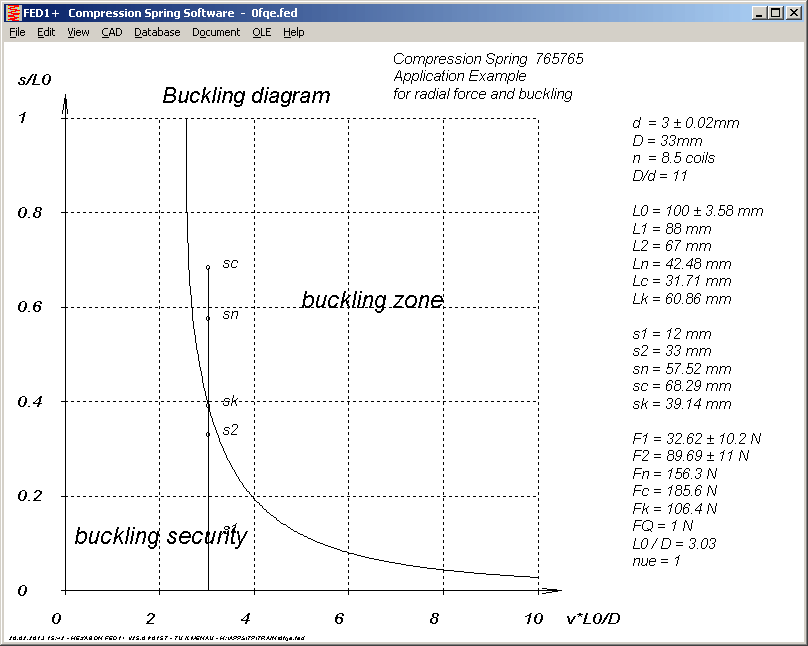
In the buckling point sk, transverse spring travel grows infinite, radial spring rate becomes 0, and radial natural frequency becomes 0.
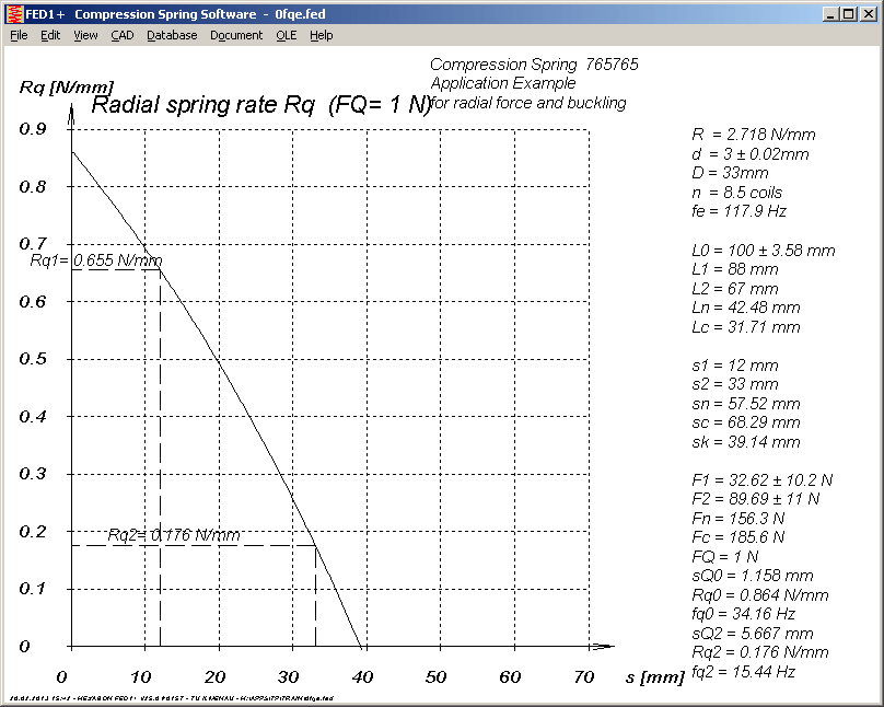
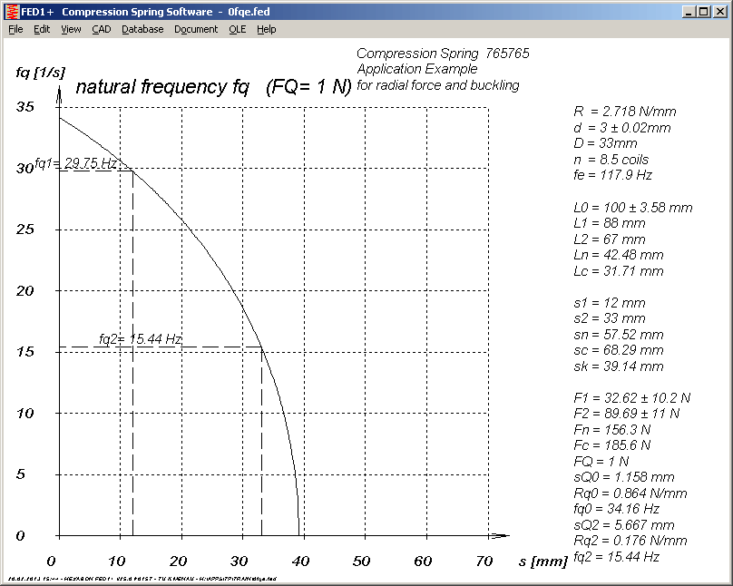
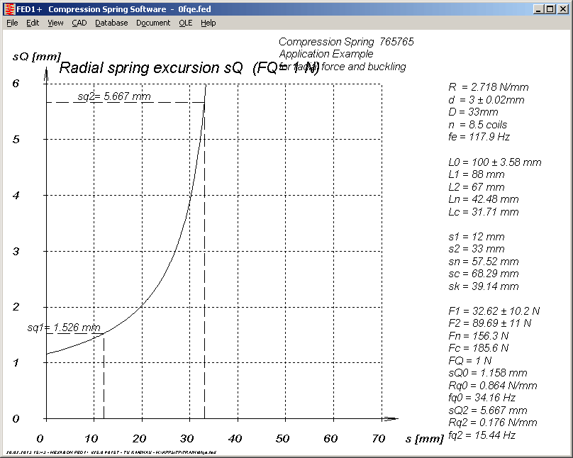
But this applies for bedding coefficient nue=1 only. This means that formulas from EN13906-1 for calculation of transverse deflection sQ are valid for bedding coefficient nue=1 only. FED1+ now shows a new error message, if you entered radial load FQ, but bedding coefficient nue is not 1.
FED1+, FED2+, FED3+,FED9 W-s Diagram
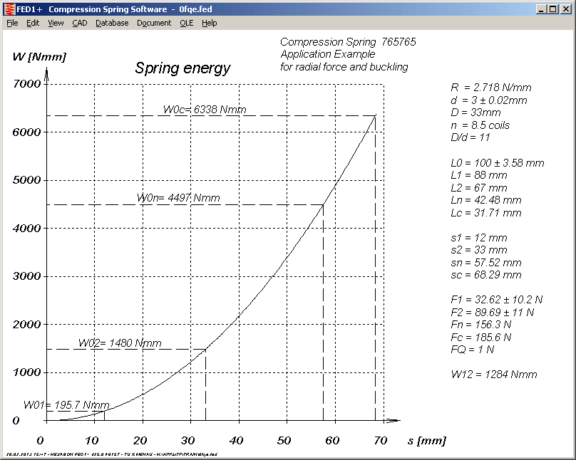
A new diagram with spring energy as function of spring travel W = f(s) has been added into FED1+, FED2+, FED3+ and FED9.
FED4, FED5, FED6, FED7: W12 added to W-s Diagramm
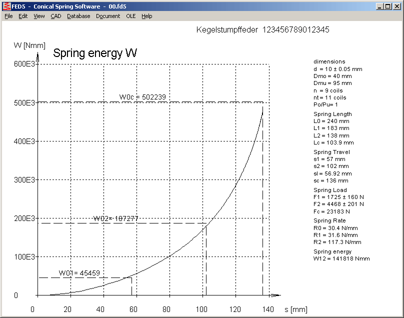
Spring energy W12 between spring travel s1 and s2 (W12 = W02-W01) has been added or modified in FED4, FED5, FED6, and FED7.
FED1+ Fn' added to load-deflection curve of spring
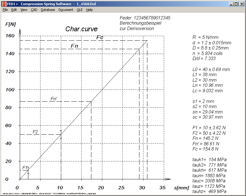
At compression springs, index n stands for usable spring travel until safety distance Sa before solid length. At extension springs and torsion springs, index n stands for usable spring travel until permissible shear stress or bending stress.
For block-safe compression springs, shear stress tauc c is less than permissible shear stress tauz. In case of taun > tauz, a new line Fn' is drawn in the load-deflection curve at taun' = tauz.
FED2+ Dimensioning or Recalculation after Modifications, Natural Frequency
After modifications of pretension (Edit -> Production) or loops (Edit -> Loops), you can select if FED2+ should dimension or recalculate the spring. At dimensioning, loads remain unchanged. With recalculation, spring dimensions remain unchanged.
And in Quick3 view, natural frequency "fe" of the spring body has been added, also for extension spring of rectangular, quadratic or elliptic wire now.
Spring Materials - Chemical Composition
Some rather cosmetic changes were done in the spring material database (fedwst.dbf). For some high-alloy spring steels, designation was changed in the EN standards. X12CrNi17-7, for example, was renamed into X10CrNi18-8. Chemical composition was not really changed: carbon max. 0.12%, chrome 16-18%, nickel 6-9%. We have updated new designations also for older Sandvik materials now:
12R10, 11R51: X10CrNi18-8
13RM19 (non-magnetic): 1.4369, X11CrNiMnN19-8-6
5R62: X5CrNiMo17-12-2
SAF2205: X2CrNiMoN22-5-3
2RK66: X1NiCrMo25-20-5
9RU10: X7CrNiAl17-7
8R70: X6CrNiMoTi17-12-2
WN10 - Tolerance System according to DIN 5480 and DIN 5482
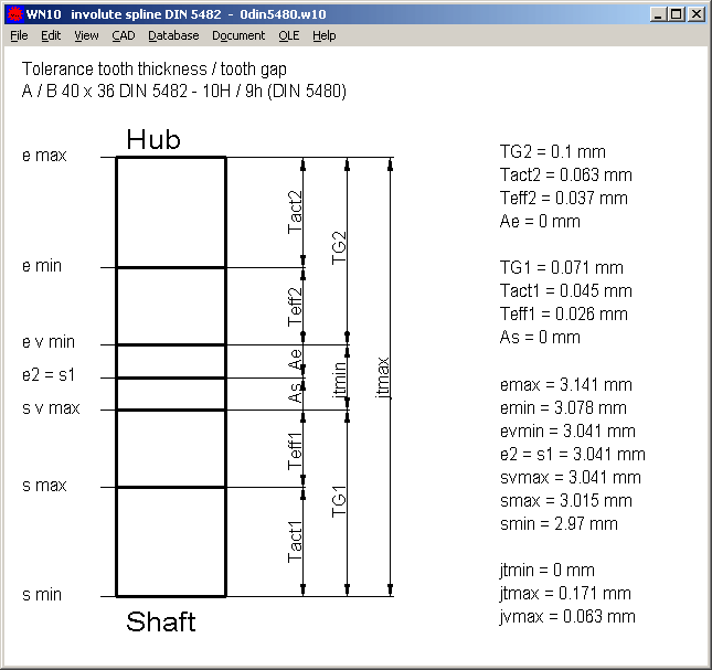
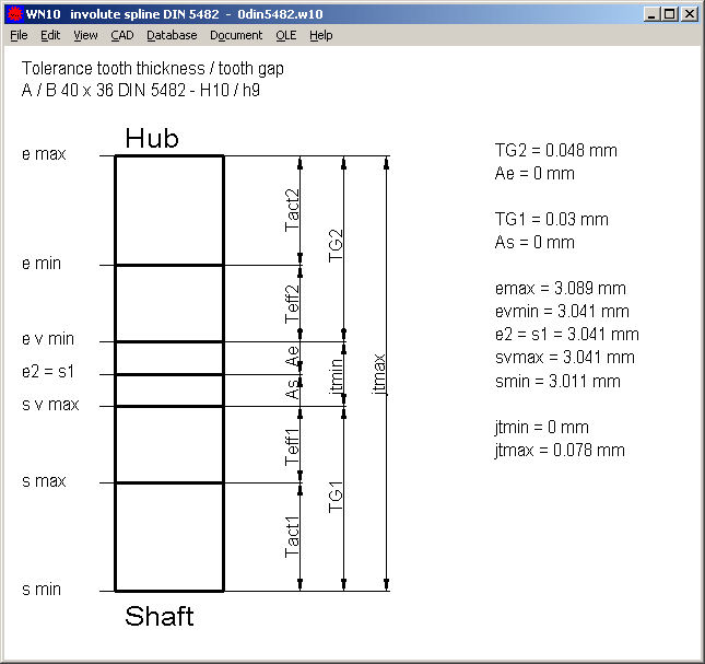
Until now, WN10 included tolerance system according to DIN 5480 with multiple choice of tolerance series "4" .. "12" and tolerance zone "a" .. "v" for external spline and "F" .. "M" for internal spline. The withdrawn standard DIN 5482-3 of 1973, however, defines another tolerance system. Internal spline tolerance is fixed to ISO tolerance "H10", and for external spline you can select between e9, h9 und k9. The ISO tolerance is based on tooth thickness sw (external spline) and gap width lw (internal spline). Dimensions over/between pins are calculated from this dimensions. Deviations of profile and pitch, actual and effective dimensions are not considered in withdrawn DIN 5482-3:1973. Nevertheless, WN10 includes now two tolerance systems, at "Edit -> Quality" you can select between tolerances according to DIN 5480:2006 or DIN5482:1973.
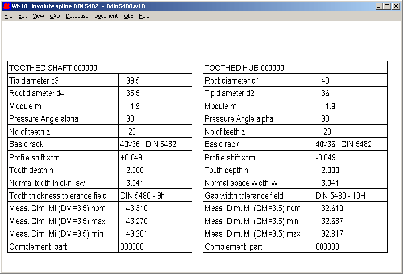
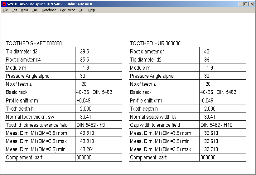
In printout of WN10, max.effective torsional backlash jvmax has been added (for DIN 5480 tolerance system), and all values for torsional backlash in degrees.
In WN10 printout, number of teeth and over pin dimensions are printed with negative sign according to DIN conventions. In graphic tables, dimensions are printed without sign, so min and max had to be exchanged in the internal spline table.
WL1+ Automatic Dimensioning
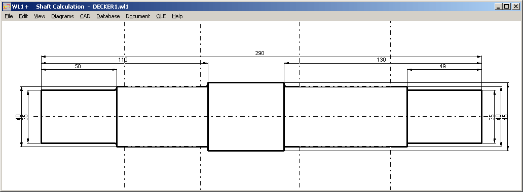
Until now, shaft diameters were dimensioned directly at the shaft segments. Now you can set option at "CAD->Settings" to dimension diameters outside the shaft.
ZAR1+ Calculation Methods
After input of a load spectrum, you have to decide if application factors should be calculated from load spectrum or not. Now you can preset that application coefficients KAH and KAF always should be calculated from load spectrum. In the same way you can configure that pin and ball diameter for dimensions over/between balls always should be calculated by ZAR1+ (according to DIN 3960).
The new pre-settings are helpful if you use ZAR1+ in command line mode to perform many gear calculations in short time.

ZAR6 - Tolerances
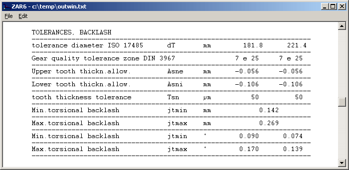
Tolerance diameter dT according to ISO 17486 is now calculated and used as reference for calculation of tolerances and deviations. Backlash jtmin and jtmax has been added (without consideration of center distance tolerance and shaft angle tolerance). Moreover, several mounting dimensions and toothing dimensions have been added to printout (LA, LD, LW, sin, sinmin, sinmax, h'ai, dB, tH, tB).
Save Menu Language
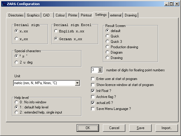
At "File->Settings->Settings", you can now check if selected menu language should be saved in configuration file or not. Until now, it always had been saved.
Terminal Server
Network floating licenses of HEXAGON Software can be used on a terminal server, too. Floating license on a terminal server can be installed with setup.exe, like an individual license on a standalone computer. Installation of individual license on a terminal server, however, violates license contract and is forbidden.