 | English
| Deutsch
FED2+: Extension Springs with insert loops

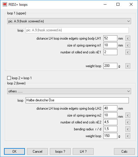
No loop is drawn now if hooks or screws are rolled in or screwed in, a descriptive text and a dash-dot line at LK and LH is drawn instead now.

FED2+: Weight of inserts
For rolled-in or screwed-in hooks or screws, you can now enter the weight of the insert or the loop, these are then added to the weight of the tension spring.
FED2+: Bending radius of loops
The bending radius can now be entered separately for loop 1 and loop 2. Nothing changes in the calculation of the bending stress, the smaller of the two values is decisive.
FED2+: Loop position with threaded bolt
When threaded studs are screwed in or tension spring without loops are calculated, loop position is no longer displayed in the Quick3 view.
FED6, FED7: Numbering coil sections
Because the spring is displayed vertically on the screen, the two spring ends are named "top" and "bottom". When entering the coil sections, you start at bottom, section 1 is the bottom section of the vertical spring. For the end coils, E1 is the lower end coil and E2 is the upper end coil. The table with the coils started with 1 (top) and ended with the last turn (bottom). Because this is reversed as in the illustrated spring drawing, the table is now shown reversed: first upper end coil E2, then starting with the last coil down to the first coil and end coil E1. Nothing changes in the production drawing, where the coil table is displayed "lying".


FED7: Calculate compression springs connected in series
FED7 can also be used to calculate stacked compression springs. To calculate the block length, you can enter the compression springs in 2 or 3 sections: End coils and active spring coils. End coils with L0i = nE * d, however, one can not distinguish between end coils lined-up and raw or ground, so the FED7 calculation is not quite accurate for spring stacks.
Calculate compression springs connected parallel
When compression springs are connected in parallel, the suspension starts with L0 of the longest spring and goes to block when the first spring goes to block. It was requested to make new software for parallel connected springs. If there is more demand, we can do so.
ZAR1+: Design eccentric gear with ZAR1 +

In the newsletter 167 one year ago was shown how to calculate externally and internally toothed gear wheel for an eccentric gear by means of ZAR1+. There were demands for this, so here is the procedure with ZAR1 +. In the example from Info 167, the number of teeth difference was 2 teeth, but in order to achieve a high gear ratio, the rolling gear wheel should be smaller by only one tooth than the ring gear. Usually the ring gear is fixed, the rolling gear is driven by an eccentric shaft. Eccentricity is the calculated center distance. On the output side, the rotation of the rolling gear wheel is taken around the center, which is done here by a disc with bolts and rollers on a bolt circle, which dip into holes in the rolling gear. Bore diameter in the rolling gear wheel is the roller diameter + 2 * eccentricity. An eccentric gear with an involute gear pair is a cost-effective alternative to similar gear designs with cycloidal gear, wave gear, cyclo drive, harmonic drive, galaxy gear, etc.
An eccentric gear is useful if you want to realize a high translation with only one stage. The highest possible translation is achieved when the number of teeth difference is as small as possible: one tooth. Example: with number of teeth rolling gear wheel +30 teeth and ring gear -31 teeth is the gear ratio -30, the direction of rotation of the input and output shafts is opposite. If you lock the bolt plate and drive off the ring gear, the gear ratio is even bigger (+31), and the direction of rotation is the same as with the eccentric drive shaft. If you hold the eccentric shaft, ring gear and bolt plate run in the same direction, the speed is different by the gear ratio 31/30 = 1.0333. For example, if the bolt carrier rotates at 1000 / min, the ring gear rotates at 967.7 / min.
GR2 will be a new calculation program for eccentric gearboxes. GR2 calculates eccentric drive shaft, output shaft with bolt plate, and all of the rolling bearings. But not the gears, you can with ZAR1 +. Or you use cycloids, wave gear, or even friction gear.
ZAR1+ calculates the gear wheels for the eccentric gearbox: rolling gear +30 teeth, ring gear –30 teeth.

The first experiment with z1 = 30, z2 = -31, alpha = 20 °, x = 0, tooth height (1 + 1.25) * mn. Of course that's not how it works.

Second trial with halved tooth height factors (tooth height (0.6 + 0.5) * mn).

Now the pressure angle is changed from 20 ° to 45 °. Still meshing interferences.

Fourth attempt with profile shift x2 = -0.5. Negative profile shift increases the ring gear or reduces the rolling wheel, here with x2 = -0.5, x1 = 0. No meshing interference anymore. However, the calculated operating pitch circle is far outside the toothing, the calculated operating pitch circle diameter is almost twice as large as the pitch circle diameter. But the animation shows that the gearing can be used for this application.
There is no line contact on the calculated pressure path, but 2 contacts about two or three teeth left and right of the centerline. Negative with regard to friction and sliding, but positive in terms of load capacity and torsional backlash and self-locking. You have to ignore the error message in ZAR1+ because of pitch diameter, pressure path and epsilon alpha <1.

But you can also set the profile shift back to 0, and further reduce the tooth height factors to (0.5 + 0.4) * mn, so that one also reaches the goal.

Although gear ratio, modulus and pitch circle diameter are the same for both variants (i = 30, mn = 1mm), the eccentricity of the eccentric shaft differs: without profile shift a = 0.5 mm, but with profile shift (x2=-0.5) a = 0.916 mm, almost twice as large. Major diameter and minor diameter of the profile-shifted ring gear are both larger than the pitch circle.
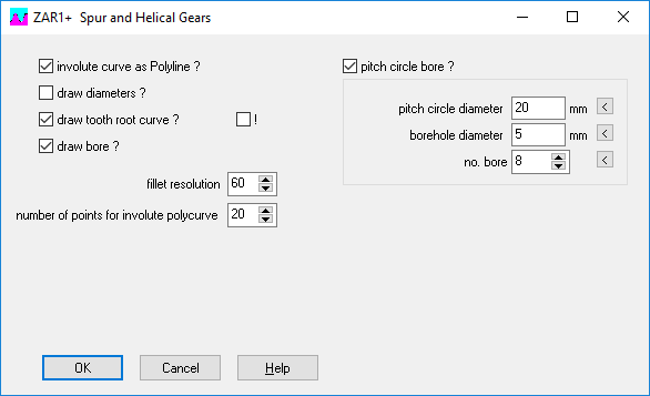
For the production of model gears with 3D printers, you can enter a bolt circle with holes in ZAR1+ under "STL \ Gear1,2":

For the ring gear, define the holes for bolts. And for the rolling gear, define the holes for the rollers of the output shaft. For the ring gear, the entered bore diameter is the outer sprocket diameter.


When the ring gear and the gear wheel are finished, you can use GR2 to create the drive shaft, output shaft and bearing cap as STL files and produce with 3D printer.


The produced model gearboxes from the 3D printer with a gear ratio of 1:10, 1:30 and 1: 100 work great, only a bit loud at high input speed.

GR1: Eccentric gear added


Eccentric gearboxes were added to the gearbox software GR1. The relative speeds can be calculated similarly to a planetary gear. The rolling gear wheel is the planetary gear, the eccentric shaft is the sun gear, the bolt plate is the carrier, the ring gear remains ring gear. The virtual number of teeth of the sun gear is the negative number of teeth difference: zS = zH + zP. The gear ratio with blocked carrier is i0 = zH / zS = zH / (zH + zP). The stand ratio i0 is positive, comparable with a plus planetary gear.
GEO5 Demo version
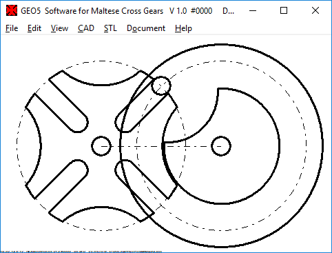
A demo version is now available of GEO5 for Maltese cross gears (Geneva drive).

All programs: Automatically load initial file
With a NULL file, factory default settings, e.g. material and tolerance classes of the machine elements are loaded automatically at program start. However, the NULL file is loaded from the configured folder, and this can be configured differently for each user's network version with many users. If every user should start his calculation with the same starting data, the administrator can now save a calculation file with the file name "INIT" in the program folder (eg "init.fed" next to "wfed1.exe"), then this INIT file is loaded automatically at program start , If there is both a NULL file in the data directory and INIT file in the program directory, the INIT file has priority.
Nitric oxide is thicker than air - at eye level with the exhaust gas sensor
The density of air at 0°C is 1,293 kg / m³, the density of NO2 is about 3,6 kg / m³. Thus, it is likely that the nitrogen oxide clouds waft on the ground. Consequently, near-earth measurements may show higher nitrogen oxide concentrations. Interesting would be comparative measurements at different measurement heights. Also interesting would be a comparison along the same street with exactly the same traffic, once along a street canyon, and then at a place without immediate development. Further parameters would be wind speed, temperature, air pressure. Unfortunately NOx meters are not available on the market, otherwise you could measure yourself. When the nitrogen oxide gas collects on the ground, the correct height is the size of a toddler who can already walk. A child at eye level with the NOx sensor. It is different with carbon monoxide. The density of CO is 1.25 kg / m³, which is lighter than air. Carbon monoxide escapes upwards. It becomes dangerous in closed rooms with a low ceiling. The young people who used an emergency power generator for light and music in a hut died by carbon monoxide poisoning. By nitric oxide and fine dust, it takes longer. Asthma has become the most common chronic disease in childhood and adolescence.