English
Deutsch
HEXAGON Info Letter No. 47, February 1998
Copyright by HEXAGON Software 1998
FED6 - Dimensioning
The newest FED6 version can now calculate the appropriate
compression spring, when the some points of the progressive
spring characteristic curve are entered. You can enter up to 50
spring travels and spring forces. FED6 then calculates the
appropriate cylindrical compression spring.
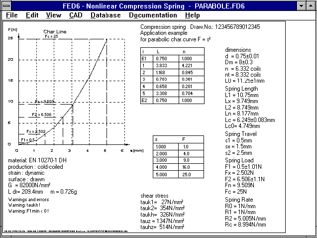 The picture shows a spring with a parabola shaped characteristic
curve. According to the function F(s) = s▓, five points for the
spring curve are entered: F(1)=1, F(2)=4, F(3)=9, F(4)=16 and
F(5)=25.
FED6 - Natural Frequency
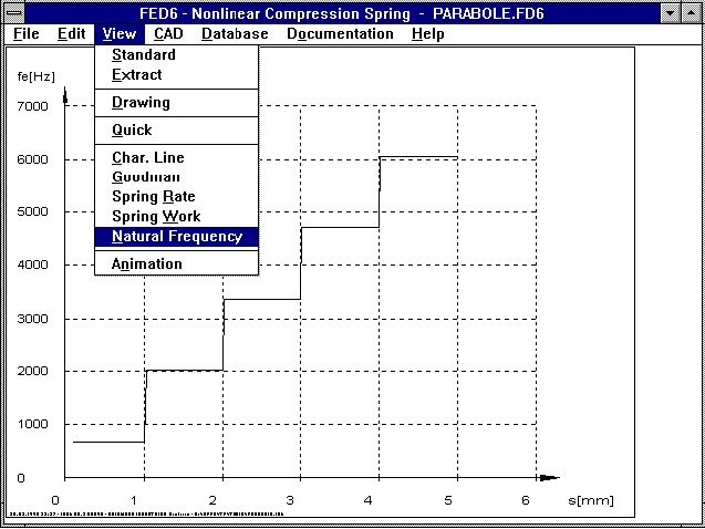 The natural frequency of a non-linear cylindrical pressure spring
changes along the spring path. The new version of FED6 shows in a
diagram, the natural frequency in relation to the spring path.
SR1 - Working Temperature
TEMPERATURE
======================================================================
Reference Temperature T0 °C 20
----------------------------------------------------------------------
Working Temperature T °C 300
----------------------------------------------------------------------
Difference Length screw delta LS mm 0.515
----------------------------------------------------------------------
modulus of elasticity screw ES N/mm▓ 206000
----------------------------------------------------------------------
modulus of elasticity screw 300 ES300 N/mm▓ 185000
----------------------------------------------------------------------
CLAMPING COMPONENTS (T = 300°C)
======================================================================
i l20 [mm] l300 mm E N/mm▓ E 300 d20 mm/N d300 mm/N
======================================================================
1 60.000 60.193 210000 185000 0.218E-6 0.247E-6
----------------------------------------------------------------------
2 50.000 50.364 44000 23008 0.601E-6 1.150E-6
----------------------------------------------------------------------
3 50.000 50.126 125000 104462 0.212E-6 0.253E-6
----------------------------------------------------------------------
Difference Length clamping pieces delta LP mm 0.683
----------------------------------------------------------------------
Elasticity screw delta St mm/N 2.464E-6
----------------------------------------------------------------------
Elasticity plates delta Pt mm/N 1.65E-6
----------------------------------------------------------------------
yield point screw Re N/mm▓ 940
----------------------------------------------------------------------
yield point screw 300°C Re300 N/mm▓ 705
----------------------------------------------------------------------
Dec./inc.clamping force Work.temp.delta FM N -40831
----------------------------------------------------------------------
assembly prestress. force 300°C FM 300 N 290196
----------------------------------------------------------------------
For differing elasticity modulus of screw and clamping plate, a
higher or lower surrounding temperature causes an increase or
decrease of the clamping force. Also, with high temperatures, the
yield point and the E modulus decrease. SR1 calculates the
temperature dependent values, these are then printed out on an
additional page. The least favourable values of room and working
temperatures are used in the safety margin calculation.
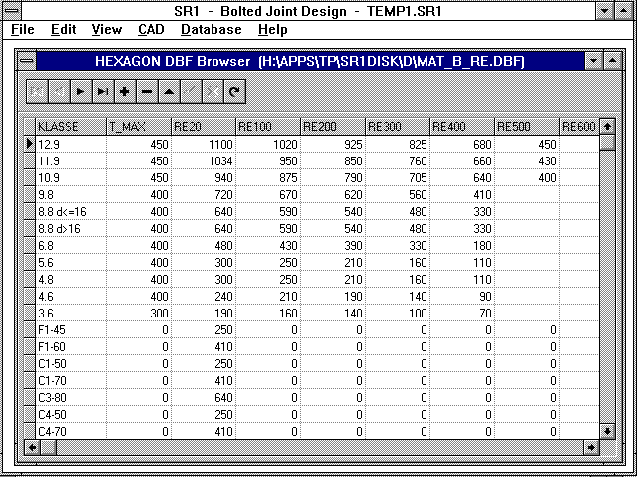 Yield point and E modulus as functions of the temperature, are
delivered as DBF data base files. SR1 interpolates the
mid-values. The data base files can be appended and altered by
the user.
SR1 - FM-MA Diagram
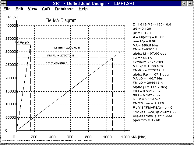 New in our screw program, SR1, is a diagram for clamping force in
relation to the tightening torque. The line for the theoretic
case without thread and head friction (ŠG=ŠK=0) is also drawn.
The diagram also shows that most of the tightening work is
absorbed by friction. The more friction there is, the lower the
target clamping force is (end of the line, yield point, screw).
HPGLMAN, DXFMAN - ARISTO Format
In the HPGL Manager and DXF Manager it is now possible to create
an initialize file, which during conversion to the ARISTO plot
format is automatically inserted into the ART file. Changes have
also been made to the conversion of poly lines and arcs which are
now drawn as a continous line.
FED1 Deviations e1, e2
The permissible deviations of the mantle curve for perpendicular
and permissble deviations of the parallelity are now only given,
in accordance with DIN 2089, when the spring ends are ground or
forged (for pre-heated springs).
DXF with AutoCAD 14
AutoCAD 14 has been having problems with the line "$ACADVER" in
the header, this is caused by the source program. For this
reason, this line will no longer be included.
When loading DXF files in
AutoCAD, please note that DXF files (with block definitions) can
only be loaded into empty documents, neither blocks or layers may
be predefined!
Dutch Spring Drawing
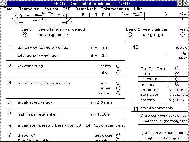 We are now able to provide versions of the spring programs,
FED1+, FED2+, FED3+, FED5 and FED6 in which the production
drawings are printed out in Dutch. However, the rest of the
program is still in German.
Goodman Diagram for Spring Programs
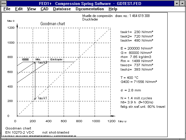 The permissible elevation stress of dynamically loaded springs
can be improved by around 20% by shot blasting. This represents
an increase in life expectancy of around 800%. The new versions
of the program calculate with a 20% higher permissible elevation
stress when there is no data for shot blasting in the data base.
This replaces the message "no material data available". The
warning "approx. Goodman" means that there are no exact data
available in the material data base. The calculation of the no.
of repetitions and life expectancy has been improved and is now
only displayed with one decimal place to avoid the suggestion
that they can be calculated to an accuracy of three decimal
places.
WN1 Micro sliding
---------------------------------------------------------------------
Shearing modulus G N/mm▓ 82692 82692
---------------------------------------------------------------------
Shearing stress, shaft tau I N/mm▓ 24.5
---------------------------------------------------------------------
Shearing stress for slipping tau R N/mm▓ 4.9
---------------------------------------------------------------------
Transfer.torque for slipping T R Nm 795.7
---------------------------------------------------------------------
Rotation, hub phiA ░ -0.0011
---------------------------------------------------------------------
Rotation, shaft phiI ░ 0.0284
---------------------------------------------------------------------
Torque limit, drift Tgrenz Nm 137.7
---------------------------------------------------------------------
Safety again. micro slipping Tgr./T 0.229
---------------------------------------------------------------------
Stress concentr.coeff. alpha kt 1.061
---------------------------------------------------------------------
For large alternating torques micro sliding can occur in the seam
surface due to differing rotations of the shaft and hub. This
causes fitting corrosion, which drastically reduces the life
expectancy of the pressed fit. The calculation is documented in
the German book "Shaft/Hub Joints" by Kollmann (Publisher:
Springer). The following measures are recommended for driftless
transfer:
When the E modulus of the shaft and hub is the same, the
diameter ratio value, QA=DA/DF, of the hub, should not exceed
▀.5.
When materials with different E modulus are select, the
shaft must have the greater shearing modulus.
For predefined dimensions, strive for increased seam
pressure.
WL1/WL1+ Bearing Rigidity
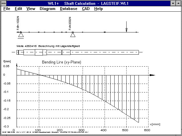 Until now, WL1/WL1+ have calculated with an infinitely great
rigidity for the bearing positions. The deflection at the bearing
positions was zero. In the new version you can, alternately,
enter the spring rate [N/mm] of the bearing position. Then,
WL1/WL1+ will take bearing bending into account. The bending line
of the bearing position then no longer goes through zero, but is
equal to w=F/c. The bending critical torque is therefore reduced.
WL1/WL1+ Quick Output
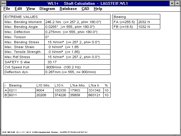 The bending critical torque has been added to the quick output.
WL1/WL1+ SchemaWL1/WL1+ Bending Critical Torque
The bending critical torque can now be calculated for 3, 4 and 5
mounted shafts. Until now the bending critical torque has been
calculated according to the Kull and Dunkerley method
(Literature: Bohl, Str÷mungsmachinen 2, Publisher: Vogel). The
method according to Kull is usually more accurate and requires
less calculation time, for this reason the Dunkerley method can
now be dropped.
WL1+, LG1 - Roller Bearing Rigidity
Approaching step by step, the bearing rigidity can be calculated
from the overstrain of the rolling element and the bearing bush.
It is not constant, but dependent on the bearing force. For
smaller supporting forces, the rolling bearing rigidity is low.
This can lead to problems with low-loaded fast moving shafts
because the critical speed is very low. By pre-stressing the
rolling bearing, or using rolling bearings with negative
clearance, the bearing rigidity can be increased. For later
versions of WL1+ and LG1, we are planning calculation of bearing
rigidity for the selected rolling bearings in relation to the
load.
WL1/WL1+ 50 Shearing Forces
The maximum number of radial forces has been increased from 20 to
50. This means that up to 50 mass forces can be calculated
according to Kull for the critical speed. The error message
"Kull: m>20" has been dropped.
LG1/WL1+ Skew-Angle Roller Bearing
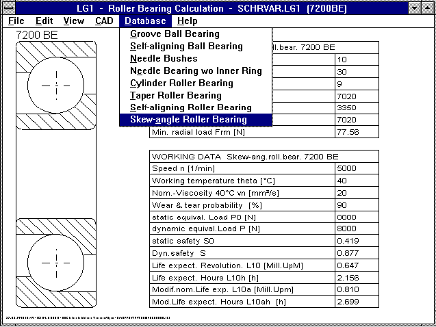
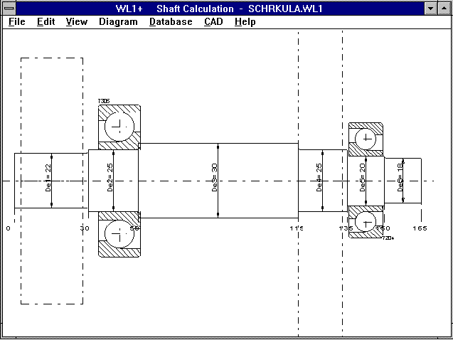 LG1 and WL1+ now include calculation, data base and drawing
creation for skew-angle roller bearings.
LG1/WL1+ Bearing Play
For grooved ball bearings the creation of reference load from the
bearing play is dependent upon the ball bearing used. The
selected bearing type (bearing play normal, C3, C4 or user
defined) is now printed out as well.
WL1/WL1+ Accepting shaft sections as additional mass
Under Edit->Calculation you can automatically accept shaft
sections as additional mass for the calculation of the critical
speed. For the calculation of the critical speed, the program
calculates with point masses which lie in the x-coordinates of
the additional mass or take effect at the center of gravity of
the shaft section. For long shaft sections, or non-stepped
shafts, this is too inaccurate. By dividing the shaft up into
several equal sectons, you can increase the accuracy of the
critical speed calculation.
The same applies for additional mass. When additional mass is
distributed over a relatively long distance, or passes through a
supported position, there is the danger of inaccuracy during
calculation of the critical speed. You must imagine that the
center of gravity for an additional mass is exactly at the
support position. The deflection is then zero, this causes the
spring constants and natural frequency to be infinitely large.
Realistic values can be obtained by dividing the additional mass
into two sections taking affect to the left and the right of the
support.
WL1/WL1+ Dynamic Bending Line
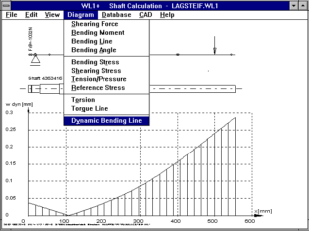 Due to the static deflection of the shaft, additional forces
develop caused by the unbalance of the shaft mass with
F = m * omega▓ * r
with omega = 2*PI*n
with
F: dynamic radial force
m: mass in Kg
omega: rotation frequency
n: shaft rotational speed 1/s
r: deflection at the mass center of
gravity.
After recalculation, the increased deflection due to unbalance
can be used for the calculation of F dyn, until balance is
attained.
WL1/WL1+ Resonance and Damping
By taking the transfer function into account, the dynamic
bending line in the resonance range is increased, and weakened
in the area the other side of the natural frequency. The
degree of damping is around 0.1 to 0.2 for steel shafts.
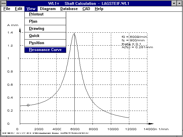 A diagram can be created which shows the deflection at any x
coordinate on the shaft in relation to the shaft rotational
speed, also taking the critical speed and damping into account.
WL1+ Locking ring
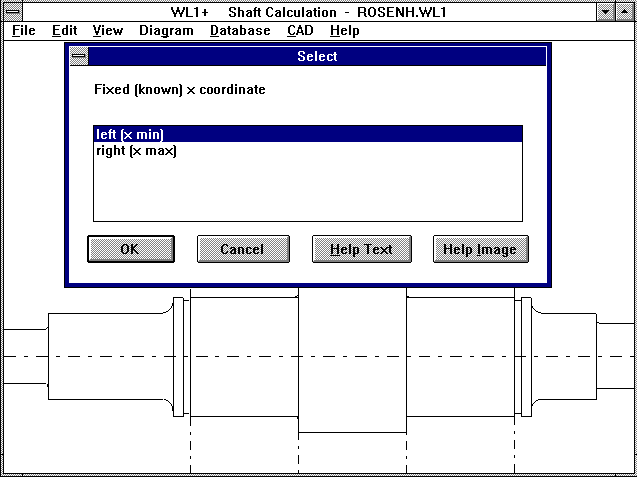 For the groove position of a locking ring in accordance with DIN,
it is now possible to enter the x position on the shaft,
determining whether it is to the right or the left of the groove.
Homepage


