English
Deutsch
Infobrief No. 44 for July/August 1997
Copyright by HEXAGON Software 1997
Result Printout for Intranet and Internet
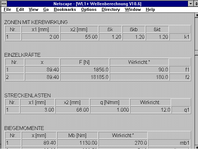
Text printout in HTML Format
The text printout for all calculation programs can now be output as an HTML file for display in
Netscape, MS Internet Explorer or StarOffice. This means that the calculation results can now
be published or archived in Intranet or Internet. The results can also be output as a table for
MS Excel or Qauttro Pro. This is ideal when you wish to work with the results in your own
programs.
Working with HTML Forms
It is possible to extend and add drawings and diagrams from the calculation program to the HTML
forms which were created by the calculation program. You can do this by loading the file into a
text program with HTML features. We recommend StarOffice 4.0 by Star-Division, Hamburg. The
created file is loaded and displayed under "File->Open". In order to insert a diagram or
drawing, change to the window with the HEXAGON program, copy the required graphic into the
clipboard with the key combination "ALT-PrtScr", change to the StarOffice window and copy the
graphic to the required position under "Edit->Insert".
FED1..FED8: Material Data Base
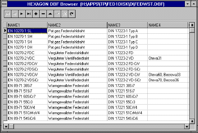 The material data for the most common spring materials, has until now been included in the
program as a fixed feature. With the new versions, the parameters are loaded from the data base
FEDWST.DBF. This provides the user with the feature for adding new materials or altering
individual values. A new field, "TMAX" for maximum working temperature, has been added to the
data base. The program provides an error message when this value is exceeded.
Spring Materials in acc. with the Euro-Norm
The new specification of materials for spring steel and valve spring wires, in accordance with
EN 10270, has now been included. The new material data base has four fields for specification:
NAME1 for the new name, NAME2 for the description, NAME3 for additional information and NAME4
for the DIN specification or company name. All four text fields are included in the standard
output. This enables the old DIN specification to be printed out during the changeover period
along with the new EN material name.
FED1+,FED2+ Searching in the Spring Data Base
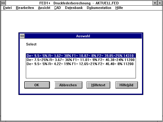 When searching for a spring in the stock list or a catalogue data base, the deviations from the
calculated spring are now provided as well. This now makes it easier to pick the most
appropriate spring when several different types are found. The search algorythm has been
improved, the wait-time while searching in a data base with more than 1000 springs is now
noticeabley shorter. The file name selected under "DataBase->File" is saved in the FED or FD2
file. With a "NULL" file you make adjust the defaults as required.
FED6 Quick Output
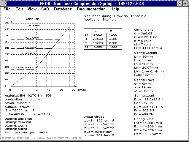 The FED6 Quick Output now includes a table with spring sections. The list of lengths and coil
numbers is displayed when the number of segments is smaller than 20.
FED7 Quick Output
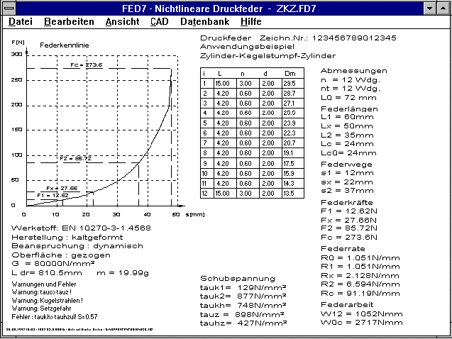 In FED6 and FED7 a table with the spring segments is now displayed when the number of coil
sections is smaller than 20.
FED3 - Conversion
Very long springs can be calculated with FED3+. When the spring path is entered in revolutions,
this must previously be converted into degrees.
1 U (revolution) = 360ø
Example: For alpha1 = 6 revolutions, you enter 6 * 360 = 2160ø.
The spring ratio is output as Nmm/ø, analog to this it can be converted into Nm/U.
1 Nmm/ø = 0.36 Nm/U
ZAR1+ Data Base Tool Profile
 Until now, the datum profile of the tooth rod could be selected from three standard dimensions,
or, the height factors, root radius and angle could be entered manually. With the new versions
(ZAR1+ only), special tools can be listed in a data base. When entering a new datum profile,
you will be asked if you wish to add the data to the data base. The ZAR1+ data base already
includes the standard profile in accordance with DIN 867, the proterberance profile, the
profile in accordance with DIN 58400 (fine tool technology) and DIN 5480 (toothed shaft), as
well as one example each for high toothing, complementary pair and profile with tip edge
fracture.
ZAR1+ Represation and Output
Under Windows, the specification for alpha kP0 and alpha prP0 were not completely shown during
the online input of the toothing profile. The English auxiliary picture "PROFIL" showed the
angle alpha kP0 incorrectly. The index for the selected picture for pinion bearing and tooth
bearing is now displayed as a letter a, b, c... instead of 1, 2, 3.. etc. The diameter is
included in the drawing for gear pair or planetary gears. I would like to thank Mr. Bertil
Jonsson of Volvo Aero Turbins in Malmo for this improvement suggestion.
ZAR1 - Complementary Toothing
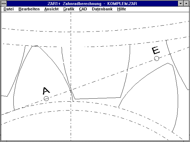 Due to the relatively low strength of plastics, the teeth made of polyamid or POM can be made
thicker and the steel teeth thinner for gear steps with a steel pinion and gear made of
polyamid or POM. This can be achieved by increasing the factor hfP0/mn of the pinion, and
reducing the factor hfP0/mn for the gear. Accordingly, the factor haP0/mn for Gear1 will be
small and larger for Gear2. In this case a special tool is required for both the pinion and the
gear, in which the head and root heights complement each other. You can load a sample file from
Internet under "www.hexagon.de/info44/komplem.zar".
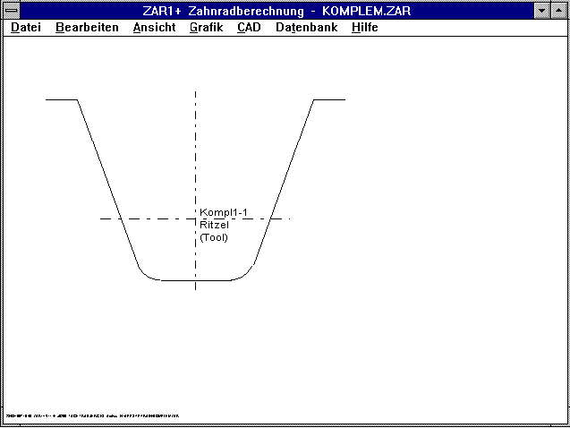 The tool for the steel pinion with low head height and greater tooth height (haP0/mn=0.65,
hfP0/mn=1.25) produces a part with a relatively thin tooth.
Complementary Toothing Gear 2
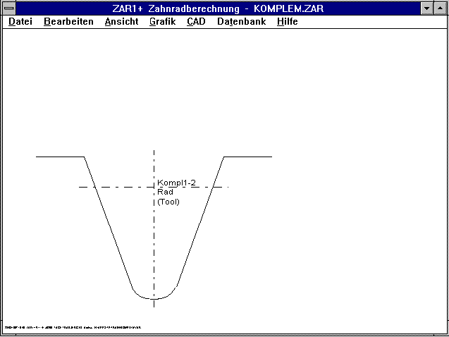 The tool for the opposing gear made of plastic, with greater head height and lower root height
(haP0/mn=1.5, hfP0/mn=0.4) produces a part with a relatively thick tooth.
WN1 - Quick Output
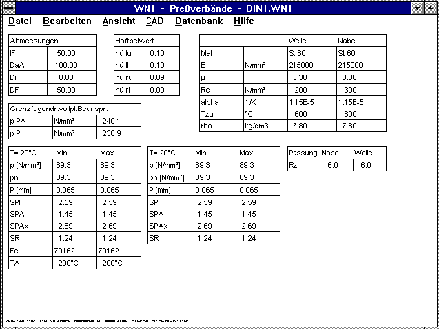 The most important data for the pressed fit and the calculation results are shown on one page
in the Quick Ouput.
WN1 - Elastic Strain
For elastic strain in the outer part, the stress in the area of the seam is constant to start
with, before dropping off. This was until now, not taken into account, the stress and seam
pressure for DF was calculated slightly too high.
SR1 - Permissible Surface Pressre
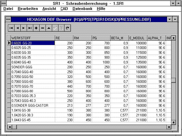 A new material has been added to the file "PRESSUNG.DBF" with the material data for the
clamping piece. Recent measurements have shown that the values for the permissible surface
pressure in Table 9 of VDI 2230 were not always correct. Some seemed too high, some too low,
and others were correct. The tables from new measures have been added to the material data
base. The existing materials, in accordance with VDI 2230 are still available, unchanged in the
data base. Several of the materials now occur twice in the data base with different values.
Until a new VDI 2230 is issued with corrected values, you can choose the current VDI 2230
values or the newer values. I would like to thank Mr Dose for providing us with the new tables.
SR1 - Flange Screws and Nuts
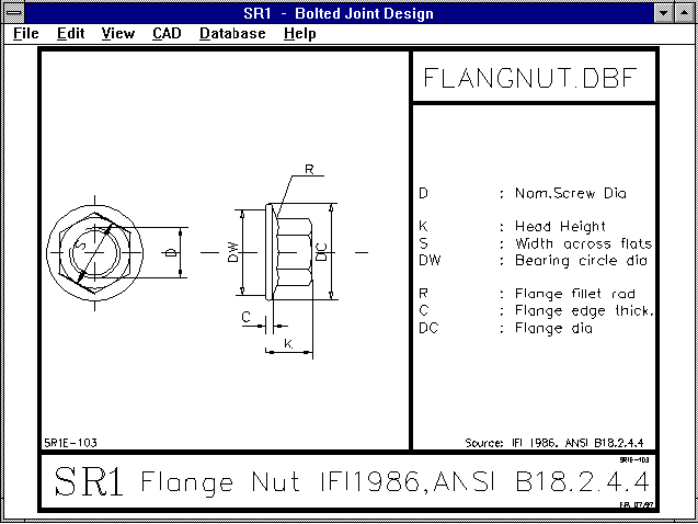 Threads in inches, help texts and auxiliary pictures have been added to the data base for
flange screws and nuts.
FED1+ in Portugese
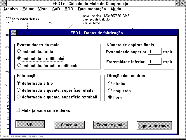 The FED1 programs for Pressure Spring Calculation are now also available in Portugese. Our
pressure spring programs are now available in seven languages: German, English, French,
Italian, Spanish, Swedish and Protugese.
WL1+ Shearing and Pressure Stress
Until now, the stress curve in WL1 didn't take shearing force affect on a bearing position, or
two opposing forces cancelling each other out into account. This is a complicated case: For
slighlty displaced force application on a sharp-edged lining surface, the shaft undergoes
shearing stress. When the opposing forces cancel each other out, the shaft undergoes pressure.
The effective cross-section can only be calculated with FEM. In most cases, the pressure and
shearing stress caused by shearing force can be ignored, because the bending pressure is far
greater. As the weakest part, caused by bending load, is at the tension side of the outer fibre
of the shaft, the pressure stress caused by shearing force does not result in an increase in
the reference stress.
When the option is set, WL1+ takes into account, approaching step by step, the shearing or
pressure stress occuring due to shearing force, by increasing the shearing stress by tau=Fq/A.
With A as the shaft cross-section with force application position. The increased shearing
stress is applied in the area of the shaft around the force application point (x-d/2 through
x+d/2).
Text Printout
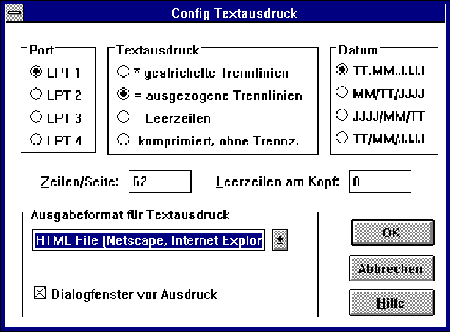 For the result printout you will asked if the printout should be displayed on screen, sent to
printer, Windows printer or sent to a file. The default until now was "Display on Screen". You
can now alter this default in the printer configuration, it is also possible to have the
question suppressed and the results printed out immediately.
HPGLVIEW - Display Cross-section
If you wish to display only a certain section of a drawing, you can enter the coordinates when
loading the program. This may be necessary when you load HPGLVIEW with one of your own
programs, and you wish to use HPGLVIEW to display different details of a compilation drawing.
Command line:
HPGLVIEW file name xmin ymin xmax ymax
- xmin/ymin is the left-hand lower corner, and xmax/ymax is the right-hand upper corner of the
displayed window in mm. - All parameters must be separated by blanks. It is also possible to
define the screen center of the diagram and the width of the displayed area, the command line
is then
HPGLVIEW file name x y l
with x and y as coordinates for the screen
center and l as the width of the screen section in mm.
Homepage


