Info Letter No. 39 Sept/Oct 1996
Modifications in Spring Drawings
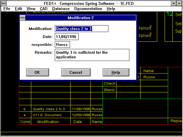 You can now enter up to 8 changes in the spring programs under "Document->Change" including description, date and name of user. The descriptions are automatically included in the change index of the
production drawing in the spring programs FED1+, FED2+, FED3+, FED5 and FED6. The drawing date, name of designer, "Replacement for" and "Replaced by" can be entered under "Drawing Info", the entries
will be included in the drawing. Altered spring drawings can easily be directly plotted out with DXFPLOT. In this way you can avoid the long way of doing this by going via CAD. Only the FED drawing
will be archived instead of the CAD spring drawing.
Company Logo in the Production Drawing
If you would like to include your company logo in the production drawing this is now possible with the new versions (although this is not too easy!): You create your company log in CAD with the
required dimensions (the enter point is located in the left-hand lower corner of the free box). Save the drawing as a DXF file with the ame "$LOGO_1.DX$". Now edit the DXF file with a text editor and
delete the all lines except those in the ENTITIES section containing the drawing information. Next copy the file into the HEXAGON temporary directory and set the attribute to "read only" with "ATTRIB
+R $LOGO_1.DX$". The HEXAGON programs look for a Logo File when outputting the production drawing and include this as a block if it one exists.
Using your own Drawing Head
If you wish to replace the whole drawing head with your own construction create a DXF file "$FRAME_1.DX$". Delete all sections except for Entities, copy the file into the temporary directory and
protect it with the Read Only attribute. Make sure you leave the spaces for drawing name, drawing number, date, designer and alteration protocoll free as the text entry positions cannot be changed.
Problems with DXF Files with Borders
With the newer Windows programs (from 15 Aug 96) you can configure whether or not the drawing should have a border under "Print Settings". When you output a drawing with a border to a DXF file
problems can arise when being exported to CAD. Please switch off the option "Border" then no problems will arise. This problem no longer occurs in versions from 24 Sep 96. DXF and IGES files are
output without a border.
Reference to Linked Documents
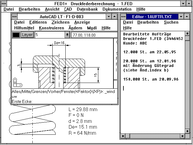 All Windows programs now include the menu item "Document". It contains the previously named description of changes, you can also make cross-references to up to 5 documents which belong to the
calculation. This can include documents from other programs, these are then configured under "Document-Setup". �2Example:�1 You are calculating a pressure spring with FED1+, the construction order exists
as a text file, the construction drawing exists as a bitmap, the parts drawing is in CAD, the cost calculation has been created with a spreadsheet program and the time plan with a project program. Now
all you have to do is configure the document under "Document-Setup" with its file name and the program it belongs to. The required document will then be displayed at the press of button. When you
click on "document 1", for example, the construction requiremets will be displayed in the Notepad Editor. Under "Document 2" the Paintbrush will appear with a construction sketch, with "Document 3"
you can load your CAD program with the parts drawing. "Document 4" will load Excel and the calculation page will be displayed on screen, and with "Document 5" you will see how far along you are in the
time plan in the project program.
Suppress License Window and Password Entry (User Entry)
With all Windows versions after October 1996 you can suppress the license window as well as the user password entry at the program start. However, as the user password entry selects the directory with
the calculation data, you should only suppress the password entry when you are the only program user and wish to save all of your data to the same sub-directory. You can enter this directory (e.g.
C:\FED1\TRAIN) in the program manager as working directory. The CFG file must then be copied into the new working directory.
TOL1 Converter
The software TOL1CON has been developed for transferring data from CAD and spreadsheets. The program imports measurement elements from Excel and Quattro Pro TXT files. The reverse is also possible,
export to TXT files for transfer to spreadsheets. Even more interesting is the transfer of measurement elements with the links to CAD via a DXF file. TOL1CON asks if the measurements should be read-in
horizontally or vertically. All perpendicular or horizontal lines are then read in as drawing elements. TOL1CON then asks for the root element 0, then creates the tolerance chain automatically from
the dimensions. Error messages are displayed for drawing elements which cannot be coordinated. The drawing dimensions can only be accepted when the dimensions in the DXF file are defined as
"DIMENSION" and used as a block. The drawing can be saved as a TOL file. The program will be available from December 1996 at a price of DM550.
Tolerance Calculation for Individual Parts and Construction Groups
A disadvantage of TOL1 is that when the dimension of one part which is used many times in different construction groups is altered, each tolerance calculation must be individually adjusted. It would
be better, if when an indivual part is altered, that this change would occur automatically in the construction groups. We are currently working on new software which will load several TOL1 files of
individual parts and create a construction group out of them. The new TOL2 software should be available by January 1997.
FED8 - Torsion Bar
We now are able to provide FED8, new software for dimensioning and re-calculation of torsion bars. FED8 has output facilities for spring characteristic curve, spring operation, Smith diagrams and
spring drawing as screen graphic and DXF/IGES file. FED8 is available from December 1996 at DM 620.
Export Function for Excel, Quattro Pro etc.
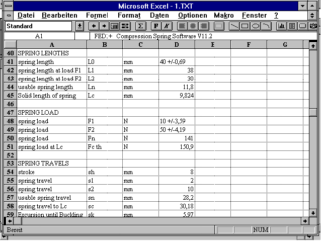 All HEXAGON programs now have a new feature for result output, along with output to screen, printer, Windows printer, file, you can now output your result data to a TXT file. This creates a text file
without drawing head and separating lines, which can be loaded and used in spreadsheet programs such as Excel and Quattro Pro. You can then work on the file, carry out additional calculations and
printout the work sheet. Quattro Pro V5.0 Windows loads and displays the file directly. For Excel you must adhere to the following settings:
File type: text file
Data type: separated
Source file: PC-8 (DOS)
Separating character: Tab
Unfortunately the TXT files cannot be read by StarCalc.
FED1 thru FED7: Life Expectancy
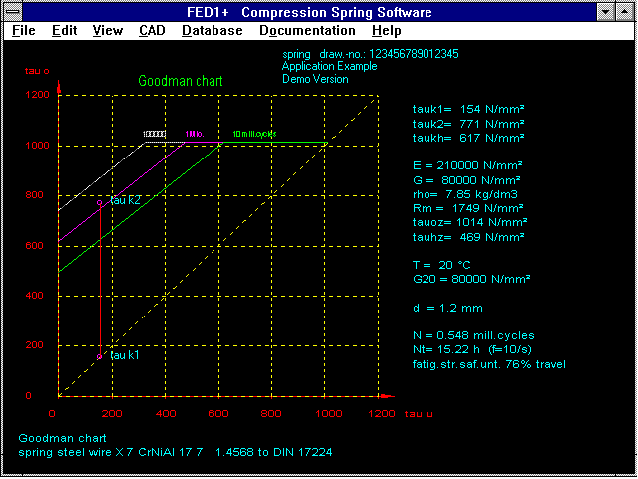 The achieveable repetitions can be seen on the Goodman diagram when the spring path lies below the upper shearing stress ço. In the new versions the Goodman diagram provides the achieveable
repetitions as a numeric value. In addition, the life expectancy is provided in hours, calculated from the repetition frequency with dynamic load. The repetition frequency lies, for example, at 30 Hz
for a spring valve with a mean cam shaft rotational speed of 1800 rpm. For a lever spring which is used approximately 60 times an hour, the repetition frequency should be entered as 0.0166.
FED1+, FED2+ Spring Data Base: Accepting Material
A field is provided for an internal material EDP number in the pressure and extension spring data base. Alternatively you can use the material number provided by FED1+ or FED2+ (from 1 to 24). When
loading a spring from the data base the material type is transferred when the material number is smaller than 24, and the shearing modulus matches the values from the FED1+/FED2+ data base.
FED1+ Diameter of von Pin and Guide Bush
The pin and guide bush diameters have not until now been saved in the FED file (for CAD production drawings). This has now been changed. I would like to thank Mr Marco Vignaroli of Benelli Armi in
Urbino/Italy.
FED1+ Warning Suppression
Under "Calculation Method" there is now a new option for suppressing the warning "End Coil < 1" and "Spring Buckling". You can use this option when the spring is guided and the number of end coils
must be smaller than 1.
WL1+ 4 and 5 times bedded shafts
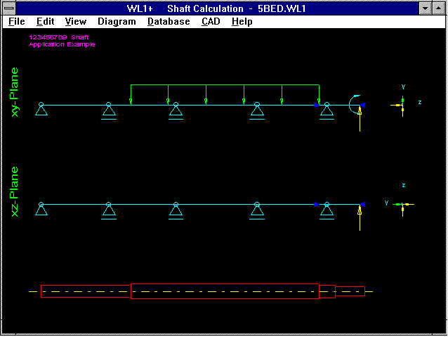 The new version of the shaft program also allows calculation of 3, 4 and 5 time support positions for statically undefined supported shafts. However, the calculation time is increased enormously. When
calculating statically undefined supported shafts don't immediately think of a system crash when the hour glass on the screen doesn't disappear right away. Time checks with a Pentium (133 Hz) produced
the following results:
2 bedding positions: 0.5 s
3 bedding positions: 5 s
4 bedding positions: 60 s
5 bedding positions: 10 min.
WL1+ Safety Margin against Fatigue Fracture
WL1+ now provides safety margins against fatigue fracture for dynamic alternating load (bending, torsion and reference stress) when the material is selected from the data base and the values Sigma bw
and tau w are available.
ZAR1+,ZAR2: Collective Load
The red load-bearing capacity lines in ZAR1+ and ZAR2 are calculated from T0, Tn, N0, Nn, Teq and Neq and cut the equivalent torque Teq at the equivalent load change number Neq. The load-bearing
capacity line and the collective load must lie below the measured damage line. The damage line is now also drawn, for this the limiting torque TnH (flank) and TnF (tooth root) are calculated as
equivalent torque (nominal torque TN multiplied by applicaton factor KA), for which SH and SF are equal to one.
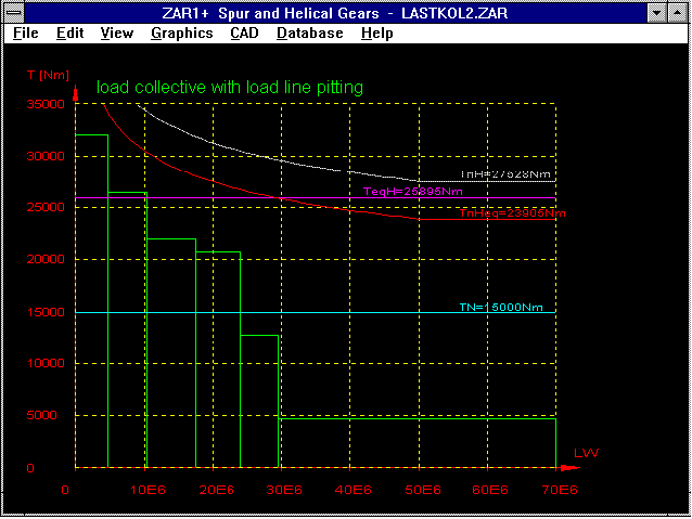 When the load is smaller than TnH or TnF (n=infinite), the gear is durable, the time-strength lies in between these values (T0 thru Tn). This means that after a certain operaton time root fatigue
fracture and pitting occur. The program calculates Tn as the torque (nominal torque TN multiplied by application factor KA) at which the gear is still durable, this means SH01 or SF=1 (the smallest
value from SH1 and SH2 or SF1 and SF2 is used). T0 is then calculated from the exponential factor of the choosen material.
ZAR2 - Input of Factors
With the strength calculation you can enter the K, Z and Y factors depending on whether you are using the DIN 3991 or Klingelnberg calculation methods. Until now the factor ipsilon (y) has not be
asked for and saved, this has now been corrected. The factors for calculation of the safety margin against corrosion cannot be entered, now however, oil temperature, oil viscosity and torque of the
test gear T1T are required and the safety margin against corrosion is calculated from these values. We would like to thank Mr Rabe of GEZE in Leonberg, Germany for drawing our attention to this.
ZAR2 - Printout without xmin and xopt
When entering the addendum modification in the bevel gear program ZAR2, the minimum addendum modification factors as well as the optimum addendum modification for same specific sliding are calculated.
In the printout the factors xmin and xopt are left out as they only cause confusion. We would like to thank Mr Steinmetz of the Bastian Company in Fellbach, Germany for this suggestion.
Setup for Windows Programs
As for the demo versions there is now a setup program available for the Windows full version which copies the files and creates a program icon in the "HEXAGON" group. The SETUP also adds a link
comment to the WIN.INI with the file extension. Now when you used the File Manager or Explorer to click on a ZR3 file the program ZAR3 will be started and the required file loaded.
Light Versions
We are now able to offer several of our programs in slimmed-down "minus" versions. The Light versions contain all functions for calculation however, the CAD interface for output of drawings to DXF or
IGES files, as well as the drawing output with DXFPLOT is not possible. In FED1- and FED2- no production drawing can be created and WN1- does not produce the test protocol. The light versions could be
an advantage for the accounts as, at a price of under 800DM the acquisition can be carried under petty cash and written off immediately. A later upgrade to the full or plus versions is possible for
the cost of the difference in price, plus update costs. There a minus versions of FED1, FED2, FED4 and WN1 available.
Tip: Loading DXF Files into CAD
When loading DXF files into existing drawings this is done at the zero point and then the file is shifted into the correct position. In order to prevent the DXF drawing mixing with the existing
drawing, you can define the complete drawing as a block, load the DXF file and shift to the correct positiong, then release the block afterwards. The reverse method of defing the DXF drawing as a
block is unfortunately not possible as most CAD systems only allow blocks to be loaded into new drawings. A second method is to load the DXF file into a new drawing, save in the internal CAD format
and then load into the required drawing.
Tip: Windows - Changing Directory
When opening files a window appears with files and directories to click on. When you wish to return to the last directory enter ".." under file name, or "\" to return to the root directory.
Spring Program Distribution in Skandinavia and Great Britain
Distribution of our spring programs for Sweden, Norway, Finland, Denmark and Great Britain is now being accomplished through Stockholm's Fjäder AB, Hudene, S-52492 Herrljunga. Stockholm's Fjäder is a
subsidiary company of our customer Lesjöfors Fjäder. The point of contact is Mr Ingemar Fredriksson, Deputy Managing Director.
Distribution of SR1 in the USA
RS Technologies in Farmington Hills, USA, is a manufacturer of analytic tools for rotation angle control tightening process for bolted joints. Torque and rotation angle are recorded. Using an
analytical process the pre-stress force can be ascertained from the torque/rotation angle curve, conclusions about the settling behaviour can also be made. Mr Shoberg of RS Technologies says SR1 is an
ideal supplement to own hard and software for the analysis of bolt joints, and is now distributing SR1 in the USA and world wide.
HEXAGON Industriesoftware GmbH
Stiegelstrasse 8
D-73230 Kirchheim/Teck (Germany)
Telephone: 07021-59578
Fax: 07021-59986
Mailbox BBS: 07021-480015 (Modem 28800..2400bps)
Mailbox BBS: 07021-959242 (ISDN 64000bps)
Director: Fritz Ruoss
Return


